47
XtrapulsCD1-a
Chapter 7 - Troubleshooting
Remark: In the
TTL incremental encoder
configuration
without HES
, the motor
Phasing
procedure must be
executed again after a
Counting
fault release.
For the
Sin/Cos encoder
configuration:
Check for the correct encoder supply voltage value
Check for the correct encoder-drive-motor ground and shield connections with regard to the recommendations
of
chapter 4
.
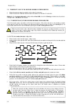
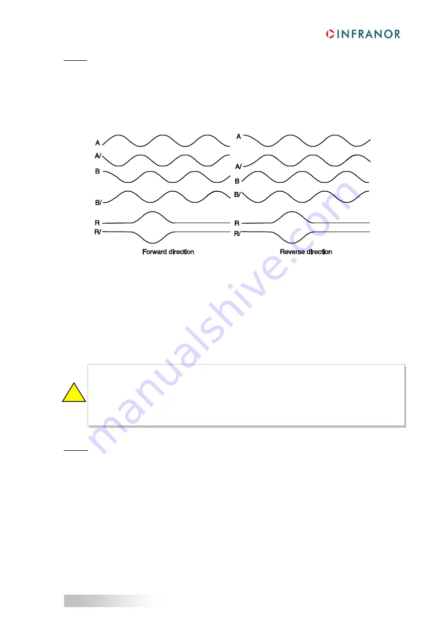
Check for the correct encoder channels A and B, and the R reference signal waveforms.
Check that the
Motor encoder resolution
and the
Zero mark pitch
parameter values are correct.
Check that the number of encoder pulses between two successive R reference signals is equal to the
Motor
encoder resolution
value multiplied by the
Zero mark pitch
parameter value. If this condition is not fulfilled,
the encoder counting protection must be disabled in order to cancel the
Counting
fault. The encoder counting
protection can be disabled by setting at 0 the
Zero mark pitch
parameter.
For a linear motor with only one R reference signal over the entire motor travelling range, the
Zero mark
pitch
parameter must be set at 15. In this case the encoder counting protection is checking that the encoder
measured position has always got the same value when the R reference signal is activated (no position
measurement drift).
Remark
: In the
Sin/Cos encoder
configuration
without HES
, the motor
Phasing
procedure must be executed
again after a
Counting
fault release.
1.11 - "HES" FAULT
For the
Incremental encoder & HES
configuration:
Check that the HES are correctly wired on the drive X3 connector (with 60° type HES, check the various
wiring combinations to find the right wiring order).
Check for the correct HES supply voltage value.
Check for the correct
Motor encoder resolution
parameter value.
Check that the HES-drive-motor ground connections and shields answer the requirements of
chapter 4
.
When the encoder counting protection has been disabled, the drive is only checking that the encoder
pulses frequency is lower than 1.5 times the maximum encoder frequency. The maximum encoder
frequency is calculated into the drive according to the
Motor encoder resolution
parameter value
and the
Maximum speed
parameter value. In this case, encoder pulse noise at a frequency lower
than 1.5 times the maximum encoder frequency may involve uncontrolled motor movements that may
be dangerous for operator and machine.
!


