13
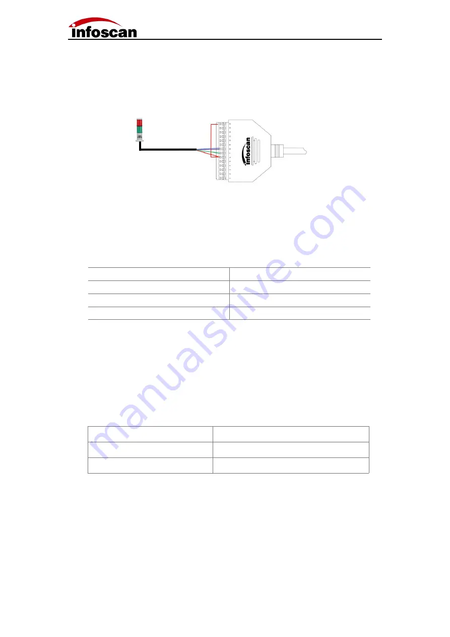
2-5 Output Wiring Diagram
1
.
Alarm lamp wiring
;
The device defaults to the initial logic and connecting pin 14 (24V) of the 14pin terminal to
the com-in terminal. Meanwhile, the positive pole of the load (taking the NPN alarm lamp
as an example) is connected to the com-in terminal and the negative pole is connected to
the out1 or out2 in output terminal. When reading is successful, the green light is on, and
when reading fails, the red light is on and the alarm sounds. The corresponding table of
line sequence is as follows
:
Note: The standard working current of output load is 350mA, and the maximum
working current is 400mA.
2.External load relay feedback wiring
;
The device defaults to the initial logic and connecting the pin 14 (24V) of the 14pin
terminal to the com-in terminal. At the same time, the relay coil end 1 is connected to the
com-in terminal and the coil end 2 is connected to the out 2 of the terminal. When reading
fails, the relay is actuated.
Relay
Terminal
Coil end 1
6
(
COM-IN
)
Coil end 2
8
(
OUT2
)
Alarm lamp
Terminal
+
(
Power input line
)
6
(
COM-IN
)
-
(
Green light
)
7
(
OUT1
)
-
(
Red light/Buzzer
)
8
(
OUT2
)


