background image

EonStor S12E-R1132-4/G1133-2 Installation and Hardware Reference Manual  

5.3.3 

DIMM Module Installation Procedure 

To replace the DIMM module: 
 

 WARNING! 

The pre-installed modules must be removed prior to installing new modules. 
Do this with care. Sensitive components can be damaged during the 
process. 


Step 1. 

Prepare an anti-static work pad or container

 for 

placing a removed module. Use of an ESD grounding 
strap is highly recommended.  

Step 2. 

Remove the BBU module,

 if installed. (See 

Section 

5.4.3, Step1

) Carefully place the module for it contains 

Li-ion batteries. Do not drop it to the floor or place it 
near any heat source or fire. 

Step 3. 

Remove the controller module

.  

Step 4. 

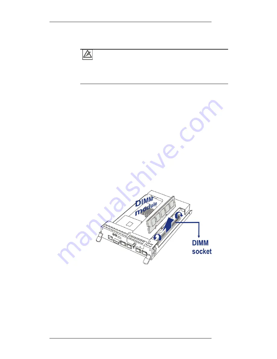
Remove the previously installed DIMM module 
from the DIMM socket

.


To do this, push the white 

module clips on either side of the DIMM socket down. 
By doing this, the DIMM will be ejected from the DIMM 
socket.  


Figure 

5

-8: Removing a DIMM Module on S12E-R1132-4 


5-12


Содержание EonStor S12E-G1133-2

Страница 1: ...EonStor S12E R1132 4 S12E G1133 2 iSCSI to SAS SATA II RAID Subsystem Installation and Hardware Reference Manual Rev 1 0 Aug 2008 ...

Страница 2: ...ing China Post code 100052 Tel 86 10 6310 6168 Fax 86 10 6310 6188 sales cn infortrend com support cn infortrend com http esupport infortrend com tw http www infortrend com cn Europe EMEA Infortrend Europe Limited 1 Cherrywood Stag Oak Lane Chineham Business Park Basingstoke Hampshire RG24 8WF UK Tel 44 1256 707 700 Fax 44 1256 707 889 sales eu infortrend com support eu infortrend com http esuppor...

Страница 3: ...eof and specifically disclaims any implied warranties of merchantability or fitness for any particular purpose Furthermore Infortrend Technology reserves the right to revise this publication and to make changes from time to time in the content hereof without obligation to notify any person of such revisions or changes Product specifications are also subject to change without prior notice Trademark...

Страница 4: ...tection against harmful interference when the equipment is operated in a residential installation This equipment generates uses and can radiate radio frequency energy and if not installed and used in accordance with this user s guide may cause harmful interference to radio communications However there is no guarantee that interference will not occur in a particular installation If this equipment d...

Страница 5: ...prevent interference with nearby radio and television reception Use only shielded cables to connec a vice is in conformity with the EMC China RoHS This de In Compliance with AeA China RoHS Regulations SJ T 11364 2006 Certified Worldwide This device meets the requirements of the CB standard for electrical equipment with regard to establishing a satisfactory level of safety for persons us CB ing the...

Страница 6: ...требования использование оборудование при температуре окружающей среды выше 50 С может привести к выходу оборудования из строя 6 Размещайте шнур питания в недоступном для пользователя месте Запрещается ставить на шнур питания какие либо предметы 7 При работе с оборудованием необходимо учитывать все предупреждения и замечания 8 Если оборудование не используется в течении длительного времени отключи...

Страница 7: ...ance with the above regulations Disposal of Old Electrical Electronic Equipment Applicable in the European Union and other European countries with separate collection systems This symbol on the product or on its packaging indicates that this product shall not be treated as household waste Instead it shall be handed over to the applicable collection point for the recycling of electrical and electro...

Страница 8: ... RAID Controller Module 1 9 1 3 4 1 Controller Module Interfaces 1 10 1 3 5 DIMM Module 1 13 1 3 6 BBU 1 13 1 3 7 Power Supply Units 1 15 1 3 8 Cooling Modules 1 16 1 4 SUBSYSTEM MONITORING 1 17 1 4 1 I2C bus 1 17 1 4 2 LED Indicators 1 18 1 4 3 Audible Alarms 1 18 1 5 HOT SWAPPABLE COMPONENTS 1 19 1 5 1 Hot swap Capabilities 1 19 1 5 2 Components 1 19 CHAPTER 2 HARDWARE INSTALLATION 2 1 INTRODUCT...

Страница 9: ...ion 4 8 4 3 1 1 Dual controller RAID to dual controller JBOD 4 8 4 3 1 2 Single controller RAID to single controller JBOD 4 9 4 3 2 Enclosure ID Settings 4 10 4 3 3 Hard Drives Installation Concerns 4 10 4 4 POWER ON 4 11 4 4 1 Check List 4 11 4 4 2 Power On Procedure 4 12 4 4 3 Power On Status Check 4 13 4 5 POWER OFF PROCEDURE 4 14 CHAPTER 5 SUBSYSTEM MAINTENANCE AND UPGRADING 5 1 OVERVIEW 5 1 5...

Страница 10: ...IONAL SPECIFICATIONS A 3 A 3 POWER SUPPLY SPECIFICATIONS A 4 A 4 COOLING MODULE SPECIFICATIONS A 4 A 5 RAID MANAGEMENT A 5 A 6 FAULT TOLERANCE MANAGEMENT A 5 APPENDIX B PINOUTS B 1 GBE ETHERNET PORT PINOUTS ISCSI HOST PORTS B 1 B 2 10 100BASET ETHERNET PORT PINOUTS MANAGEMENT PORT B 2 B 3 STP ETHERNET CABLE OPTIONAL ACCESSORY B 2 B 4 COM1 SERIAL PORT CABLE DB9 AND AUDIO JACK PINOUTS B 3 B 5 COM2 S...

Страница 11: ... screws ejection levers and the metal frames faceplates Avoid touching PCB boards and connector pins Airflow Consideration the subsystem requires an airflow clearance especially at the front and the rear An 18 to 20cm clearance is required on the rear side of the enclosure Make sure data and console cables within a rackmount cabinet are carefully routed without causing interference with the airflo...

Страница 12: ...aintain the subsystem This manual does not Describe components that are not user serviceable Describe the configuration options of firmware using terminal emulation programs or the SANWatch GUI that came with your subsystem Give a detailed description of the RAID controllers embedded within the subsystem Revision History Rev 1 0 Initial release Who should read this manual This manual assumes that ...

Страница 13: ...ion Important information that users should be aware of is indicated with the following icons IMPORTANT The Important messages pertain to using the EonStor subsystem introduced in this manual WARNING Warnings appear where overlooked details may cause damage to the equipment or result in personal injury Warnings should be taken seriously CAUTION Cautionary messages should also be heeded to help you...

Страница 14: ...ways consult technical personnel before proceeding with any firmware upgrade NOTE The firmware version installed on your system should provide the complete functionality listed in the specification sheet user s manual We provide special revisions for various application purposes Therefore DO NOT upgrade your firmware unless you fully understand what a firmware revision will do ...

Страница 15: ... device discovery For detailed iSNS service settings please refer to Firmware Operation Manual CHAP access control security Jumbo frames Header Digest mode Internet SCSI iSCSI protocols are embedded in firmware and I Os are rapidly processed via dedicated algorithms The S12E is built around reliable hardware and sophisticated RAID technologies I O requests are packaged and transmitted over local a...

Страница 16: ...133 2 can reach the maximum capacity of 60TB The S12E R1132 4 features high availability design with dual active RAID controllers Dual redundant hot swappable cooling modules battery backup and power supplies ensures the optimal up time The modular nature of the subsystem and the easy accessibility to all components ensure the ease of maintenance NOTE On receiving and unpacking your subsystem plea...

Страница 17: ... components accessed through the rear panel are referred to as Rear Panel Components 1 2 1 Front Panel Overview The front section of the subsystem features a 4x3 layout for twelve 12 3 5 inch disk drives See Figure 1 2 The two 2 handles on the front of the subsystem enable you to easily extract the chassis from a rack or cabinet The front view is shown below A description of each front panel compo...

Страница 18: ... to bottom Figure 1 3 Hard Drive Numbering NOTE Tray numbering sequence is important if one disk drive fails and needs to be replaced Replacing a wrong drive can fatally fail a RAID3 5 array Failing three drives destroys a RAID6 array 1 2 3 Rear Panel Overview The rear views of both the dual controller and single controller subsystems are shown below See Figure 1 4 and Figure 1 5 The rear panel pr...

Страница 19: ...s The hot swappable PSUs receive single phase power and deliver 5V 12V and 3 3V power to the subsystem A power switch is located on each PSU to turn the system on and off See Section 1 3 7 Cooling modules The redundant cooling modules ventilate the subsystem to maintain a cooling airflow across the subsystem See Section 1 3 8 1 2 4 Backplane Board An internal backplane board separates the front an...

Страница 20: ... swap mechanisms are incorporated to eliminate power surges and signal glitches that might occur while removing or installing these modules 1 3 1 LCD Keypad Panel Figure 1 6 LCD Keypad Panel The LCD panel See Figure 1 6 consists of a 16 characters x 2 rows LCD screen with push buttons a mute button and LED status indicators The LCD front panel provides full access to all configuration and monitori...

Страница 21: ... a rotary lock and a release button see Figure 1 9 The LED indicators signify drive status The rotary lock prevents the tray s unintentional ejection while the convenient release button ensures fast and efficient drive swapping There are screw holes on the sides of the drive tray for securing hard drives to the drive tray WARNING Be careful not to warp twist or contort the drive tray in any way e ...

Страница 22: ...e tray Figure 1 10 Dual ported SAS and Single port SAS Connectors MUX kits are equipped with active active port selectors to facilitate SATA drive installation and access from dual active RAID controllers See Figure 1 11 for how it works Figure 1 11 MUX Kit Working Theory When installed into the enclosure the SAS connectors on the other end of the MUX kits will mate with the corresponding connecto...

Страница 23: ...RAID Controller Module Figure 1 12 RAID Controller Within S12E R1132 4 Figure 1 13 RAID Controller Within S12E G1133 2 The RAID controller module that came with your subsystem contains a controller board a BBU module bay an interface faceplate and a pre installed 512MB DIMM module See Figure 1 12 and Figure 1 13 1 9 ...

Страница 24: ...omes with two 2 GbE host ports The subsystem connects to the host through RJ 45 connectors while the connectors are also ready to connect to one or more network switches enabling access to your storage volumes in complex configurations such as data sharing or Virtual LAN segments The docking connector at the rear of the controller board connects the controller module to the backplane board 1 3 4 1...

Страница 25: ...em statuses for system monitoring Please see Section 3 2 3 1 for more information Management LAN Port Another 10 100BaseT Ethernet port connects the subsystem to a management computer Available management interfaces include telnet Java based SANWatch manager or the web based Embedded RAIDWatch manager invoked by an http console settings Please see below for why and how to use this button faults be...

Страница 26: ...t for restoring ID LUN mapping after restoring defaults Default restoration will erase the ID LUN mapping associations e g which logical drive is associated with which host ID LUN and it is necessary to restore the host ID LUN mapping after firmware default restoration in order to access data on the previously configured arrays How to use the button CAUTION The Restore NVRAM Default push button sh...

Страница 27: ...ton You may ask another person to observe the message on the other side of the chassis to see if the Default Restored event appears Step 3 Power down install controller B to the controller A slot and repeat the restoration process Step 4 When completing restoring defaults on both controllers install both controllers and then power on 1 3 5 DIMM Module The controller module comes with a preinstalle...

Страница 28: ... module is only charged to between 35 and 45 of its total capacity when shipped Therefore when powering on the subsystem for the first time see Section 4 4 the BBU will begin to charge its batteries to their full capacity It normally requires approximately twelve 12 hours for the battery to be fully charged If the battery is not fully charged after twelve 12 hours there may be a problem with the B...

Страница 29: ... PSU is permanently mounted into a 2U canister especially designed to house both the PSU and a cooling module If a PSU is removed from the chassis the cooling module within is also removed Each PSU comes with a single power socket for power cord plug in and a power switch to turn the subsystem on and off A single LED indicates the PSU status If a PSU fails the LED lights steadily red An ejection h...

Страница 30: ... handle helps prevent accidental disconnection For the PSU specifications please refer to Appendix A 3 1 3 8 Cooling Modules Figure 1 20 Cooling Module of S12E R1132 4 Figure 1 21 Cooling Module of S12E G1133 2 Both S12E R1132 4 and S12E G1133 2 come with redundant cooling modules See Figure 1 20 and Figure 1 21 Below are the details about the cooling modules 1 16 ...

Страница 31: ...e remaining cooling fans automatically raise their rotation speed Elevated Temperature if the temperature reading breaches the upper threshold set for any of the interior temperature sensors the cooling fans automatically raise their rotation speed During the subsystem initialization stage the cooling fans operate at the high speed and return to low speed once the initialization process is complet...

Страница 32: ... accompanied by two 2 or three ccessive and prolonged beeps backplane board a LED Indicators statuses of individual components LCD keypad panel 3 stat Each drive tray 2 LED ach RAID controller 6 system status indicating LEDs 2 Ethernet management port status L 2 GbE host port LEDs for each port 1 LED for the Re Each BBU 1 LED S12E G1133 2 Audible Alarms The subsystem comes with an audible alarm th...

Страница 33: ... permanent damage to the subsystem can result This rule also remove it unless you have prepare Hot swap Capabilities The subsystem protects data written on hard disk drives A failed drive can be replaced while the subsystem is online without affecting the operational integrity of the subsystem Depending on the RAID level your array is c ee the table b RAID Level Max No of Failed Drives RAID 0 No f...

Страница 34: ...EonStor S12E R1132 4 G1133 2 Installation and Hardware Reference Manual NOTE Instructions on how to replace these hot swappable components are given in Chapter 5 1 20 ...

Страница 35: ...t be installed in a static free environment to minimize the possibility of electrostatic discharge ESD damage See Section 2 3 2 2 Component check Before installing the subsystem check to see that you have received all the required components See Section 0 If any items appear damaged or are missing please contact your vendor 3 Hard drives Up to twelve 12 SAS or SATA II hard drives should be separat...

Страница 36: ...e www infortrend com 5 Memory modules If you wish to replace the pre installed DDR RAM DIMM module please refer to Section 5 3 6 BBU If you wish to install a BBU to S12E G1133 2 the BBU must be purchased separately and installed prior to powering on the subsystem See Section 2 9 7 Mixing SAS and SATA drives in the same enclosure is allowed However please DO NOT mix SAS and SATA II drives in the sa...

Страница 37: ...only supports SATA drives operating at 3Gbps speed and it will be necessary you configure these drives into 3Gbps speed using its the jumpers or configuration utility 10 Rack installation The enclosure chassis can be installed into a rack cabinet using separately purchased mounting rails rear attached brackets or Infortrend s rackmount rails See Section 2 6 2 3 Safety Precautions 2 3 1 Precautions...

Страница 38: ...tlet are not obstructed Ensure proper circulation is available at your installation site and heated air exhausted from the chassis is brought away d The rack cabinet into which the enclosure is installed must support over current protection and must not be overloaded by the modules installed Other requirements such as ventilation airflow rack stabilizing features electrical earthing and electrical...

Страница 39: ...closure is installed into the rack carefully route the power cords and data cables so that power cords are not resting against data cables 11 If the enclosure is not used for a long time disconnect it from mains to avoid transient over voltage 12 For safety reasons only qualified service personnel can open the enclosure chassis 13 If any of the following situations occurs contact service personnel...

Страница 40: ...tic wristband Use antistatic strap during handling Connect the equipment end of the strap to an unfinished chassis surface Avoid carpets plastic vinyl and styrofoam in your work area If the need should arise for carrying subsystem modules from one place to another carry them in a static shielding container Avoid the contact between circuit boards and clothing the exposed circuitry on PCB boards an...

Страница 41: ...re details to connect host ports to the network or external devices 6 Power on Once the components have been properly installed and all cables are properly connected you can power on the subsystem and configure the RAID array See Section 4 4 Installation Procedure Flowchart Figure 2 2 shows a flowchart of the installation procedure As you complete each step check off the Done box on the right Plea...

Страница 42: ...er two 2 boxes contain power cords and accessory items The included accessory items are 1 A COM1 serial cable 2 Two power cords 3 A null modem 4 Printed copies of Quick Installation Guide and Unpacking checklist 5 Screws for rack mounting and fixing disk drives 6 A product utility CD containing the Installation and Hardware Reference Manual this document the Operation Manual firmware and the SANWa...

Страница 43: ... contact your vendor See the Model Rack Depth Suitable Rail Kit S12E R1132 4 22 64 to 36 inch IFT 9279CSlider36 21 to 28 5 inch IFT 9272CESlide28 S12E G1133 2 25 5 to 36 inch IFT 9272CESlide36 Make sure you have an appropriate site location and cables prepared with adequate lengths to connect to main power and other devices k or cabinet before the hard drives and the drive trays are installed the ...

Страница 44: ...an Head screws 4 04 M5 x 9mm Flat Head screws 8 05 6 32 x 6mm Flat Head screws 4 06 M5 cage nuts 4 07 Filler plates behind forearm handles 4 Table 2 1 Rackmount Kit Components Step 2 Determine the position where the subsystem is going to be installed on the rack Place the brackets into the rack and slide to adjust them to the length between rack posts as shown below Figure 2 4 Adjusting Rail Lengt...

Страница 45: ...two 2 cage nuts should be attached to the first and the last holes See Figure 2 5 Figure 2 5 Attaching Cage Nuts Step 5 Attach filler plates to the back of the enclosure s left side and right side forearms with two 2 6 32 L6 screws Figure 2 6 Attaching Filler Plates Step 6 Gently slide the enclosure into the rack until you feel some resistance That means the plastic stoppers on the rackmount rails...

Страница 46: ...nstall the subsystem Step 8 There are two 2 screw holes on each side of the chassis ears To secure the subsystem to the rack fasten two 2 M5 x 30mm Pan Head screws through the holes See Figure 2 8 Figure 2 8 Securing the Subsystem 2 6 2 Rackmounting Procedure for S12E G1133 2 Step 1 Verify the contents of your rail package The package should include the following 2 12 ...

Страница 47: ...5 Inner brackets 2 06 M5 x 10mm Truss Head screws 8 07 M5 x 30mm Pan Head screws 4 08 6 32 x 6mm Flat Head screws 10 09 M5 cage nuts 12 Table 2 2 Rackmount Kit Components Step 2 Assemble both the right side and left side front brackets with the rear brackets When fitting the brackets be sure to align the bracket joints on the front brackets with the pre drilled holes on the rear brackets See Figur...

Страница 48: ... the front rack posts and two 2 to both of the rear rack posts The two cage nuts on the rear rack posts should be aligned with the middle two cage nuts on the front rack posts See Figure 2 11 Figure 2 11 Attaching Cage Nuts Step 4 Align the screw holes on the support brackets with the cage nuts on the rack posts Place the bracket into the rack and slide the brackets to adjust them to the length be...

Страница 49: ... brackets and then fasten the screws There are cage nuts behind the screw holes Figure 2 13 Installing the Support Brackets Step 6 Attach the inner brackets to the sides of the subsystem chassis by fastening five 5 6 32 x 6mm Flat Head screws through the screw holes on the inner brackets to the chassis See Figure 2 14 NOTE The inner brackets will project 75mm from the rear end of the chassis 2 15 ...

Страница 50: ...sure into the rack carefully orient the protruding edges of inner brackets so that they fit into the metal grooves on the support brackets See Figure 2 15 CAUTION At least two people are required to install the subsystem Figure 2 15 Sliding the Subsystem into the Rack Step 8 There are two 2 screw holes on each side of the chassis ears To secure the subsystem to the rack fasten two 2 2 16 ...

Страница 51: ...me capacity can ensure that all the capacity is fully used NOTE Even disk drives by the same manufacturer of the same model and claiming the same rated capacity may not have capacity exactly the same When configuring disk drives into a RAID array you may use a slightly smaller capacity as the Maximum Disk Capacity in each individual disk drive The configuration option can be found in the firmware ...

Страница 52: ...care Hard drives are very delicate Dropping a drive onto a hard surface even over a short distance and hitting or touching the circuits on the drives with your tools may damage the drives 2 Observe all ESD prevention methods when installing hard drives 3 Use only screws shipped with the subsystem Longer screws may damage the hard drives 2 7 2 Drive Installation Procedure Step 1 Place the hard driv...

Страница 53: ...ce the hard drives have been installed into the drive trays the drive trays are ready to be installed into the subsystem WARNING All drive trays must be installed into the enclosure even if they do not contain hard drives If any drive bays are left empty the ventilation required for cooling will not be normalized and the subsystem will overheat Step 1 Make sure the rotary bezel lock is in the unlo...

Страница 54: ... Tray Front Flap Step 3 Align the drive tray with the drive bay into which you wish to insert it and then slide it in This should be done smoothly and gently See Figure 2 21 Figure 2 21 Installing a Drive Tray Step 4 Close the front flap Close the front flap properly so that the connector at the back of the hard drive can be firmly connected to the corresponding connector on the backplane board Se...

Страница 55: ...event of failing both PSUs The use of a BBU is highly recommended in order to avoid data inconsistency The BBU is an optional item for the S12E G1133 2 and can be ordered separately from your subsystem vendor You may skip this section if you are using an S12E R1132 4 redundant controller subsystem because two 2 BBUs come as pre installed components 2 9 1 BBU Warnings and Precautions Install or rep...

Страница 56: ...it or throw it These actions could damage or deform it and internal short circuiting can occur possibly causing functional defects acid leaks and other hazardous results use the BBU return it to Infortrend To install a BBU please follow these steps Step 1 a medium size Figure 2 24 If a BBU leaks gives off a bad odor generates heat becomes discolored or deformed or in any way appears abnormal durin...

Страница 57: ...pacity 2 You may check the BBU related event messages on the LCD screen or your terminal console to make sure a BBU is successfully installed and starts charging 3 The life expectancy of a BBU is more than one year However batteries life span can fluctuate depending on how many times batteries are charged An installation date record is kept in the EEPROM embedded in the battery module When the BBU...

Страница 58: ...EonStor S12E R1132 4 G1133 2 Installation and Hardware Reference Manual This page is intentionally left blank 2 24 ...

Страница 59: ... FW embedded configuration utility The firmware functions and settings are fully described in the Operation Manual that came with your system Please refer to this manual for further information SANWatch SANWatch is a fully integrated Java based Graphical User Interface GUI that came with the subsystem and can be used to monitor and maintain the subsystem locally or remotely over TCP IP network The...

Страница 60: ...r two 2 seconds on the initial screen to enter the main menu Press the ESC button to clear the current event Press the UP and DOWN arrow key buttons to select viewing items As to the MUTE button it is used to silence the alarm temporarily until the next controller event occurs For more information on how to use these buttons please refer to the Firmware Operation Manual The definitions of LEDs on ...

Страница 61: ... up steadily Once the subsystem successfully boots up with no faults the ATTEN LED will turn off 3 2 2 Drive Tray LEDs Two 2 LED indicators are located on the right side of each drive tray See Figure 3 2 Refer to Table 3 2 for the LED definitions When notified by a drive failure message you should check the drive tray indicators to find the correct location of the failed drive Replacing the wrong ...

Страница 62: ...REEN indicates that the drive bay is populated RED indicates that the disk drive has failed Table 3 2 Drive Tray LED Definitions 3 2 3 Controller Module LEDs The controller faceplate is shown below There are seventeen 17 LEDs of different types on the controller of S12E R1132 4 See Figure 3 3 and thirteen 13 on the controller of S12E G1133 4 See Figure 3 4 Their respective meanings are described i...

Страница 63: ...LED Name Color Status 1 Ctrl Status Green Amber GREEN indicates that the controller is active and operating normally AMBER indicates the controller is being initialized or has failed The controller is not ready 2 C_Dirty Amber ON indicates the following There are cached data held in memory Errors occurred with cache memory ECC errors Cached data is sustained by battery backup Battery voltage is lo...

Страница 64: ...D Definitions 3 2 3 2 Restore Default LED A restore default LED is located beneath the restore default push button on the lower right corner of the controller faceplate See Figure 3 3 and Figure 3 4 After the default is restored the LED and the firmware Default Restored event will indicate successful restoration of firmware defaults For details about how to use the restore default button please re...

Страница 65: ...ission Table 3 4 GbE LAN Port LED Definitions Figure 3 6 10 100BaseT Management Port Indicators Name Color Status Link Status Green ON indicates currently connected to a LAN LAN Activity Green BLINKING indicates active transmission Table 3 5 10 100BaseT Management Port LED Definitions 3 2 4 BBU Module LED The BBU module has an LED on its faceplate Its location is shown in Figure 3 7 and Figure 3 8...

Страница 66: ... BBU battery backup unit has been charged for over 12 hours The BBU charger will enter a timer fault state When the above conditions occur the charger circuit will enter a low power and self protection state You may correct the faults when receiving a BBU Thermal Shutdown Enter Sleep Mode event message 1 Check proper ventilation within the subsystem You may also check the readings from other senso...

Страница 67: ... 3 10 PSU Module LED on S12E G1133 2 Color Status Steadily Blinking Green The power supply has not been turned on The PSU module LED will blink when the subsystem is connected to a power source but not yet turned on Static Green The PSU is operating normally and experiencing no problem Static Amber S12E R1132 4 Static Red S12E G1133 2 The PSU has failed and is unable to provide power to the subsys...

Страница 68: ...oling module has one 1 red LED located on the right upper corner of the module itself See Figure 3 12 Please refer to the cooling module LED definitions shown in Table 3 7 Figure 3 11 Cooling Module LEDs and Cooling Fan Locations on S12E R1132 4 Figure 3 12 Cooling Module LEDs and Cooling Fan Locations on S12E G1133 2 3 10 ...

Страница 69: ...ase refer to the Firmware Operation Manual on the product CD that came with your system The alarm will also be triggered when an active component within the subsystem fails If the subsystem manager is onsite and hears an alarm he she must read the error message on the LCD keypad panel SANWatch Enclosure View or a PC terminal to determine what has triggered the alarm After determining what has occu...

Страница 70: ...harging You will then receive a message that reads Thermal Shutdown Enter Sleep Mode When the temperature falls back within normal range the battery will resume charging 3 4 I2 C The operating status of PSU and cooling fan modules are collected through an I2 C serial bus If either of these modules fails the failure will be detected and you will be notified through the various methods described abo...

Страница 71: ... automatically detected and re routed for a valid connection Connection Directly to iSCSI initiators software or hardware or via Gigabit Ethernet switches To servers equipped with iSCSI HBA better be a hardware TOE TCP IP Offload Engine card and then to client stations with an Ethernet NIC or iSCSI HBA The subsystem presents its logical volumes through SCSI like IDs and LUNs These RAID volumes the...

Страница 72: ...ata servers 4 1 3 Points of Failure The primary concern for configuring host side topologies is to avoid points of failure It is therefore preferred that two HBA cards are installed on the host side and better not the onboard Ethernet Data flow and access management should therefore be implemented to avoid access contention Infortrend s EonPath software can be implemented in order to access a RAID...

Страница 73: ...ller the one with 4 ports signifying the controller on S12E R1132 4 and the one with 2 ports signifying the controller on S12E G1133 2 A logical drive consisting of multiple physical drives A physical data link A logical association e g that between a logical drive and a host port An asteroid indicates a logical drive s assignment a preferred ownership either to RAID controller A or RAID controlle...

Страница 74: ... LD1 mapped to CH1 ID This configuration is not fault tolerant Host can access each logical drive through only one path If the path fails the logical drive will become inaccessible Figure 4 1 Sample Topology Direct attached without Fault tolerant Paths 4 2 3 Sample Topology High Availability IP SAN with Redundant RAID Controllers Component Description RAID system S12E R1132 4 iSCSI RAID managed by...

Страница 75: ...n identify alternate paths to the same logical drive RAID configuration 4 logical drives each has 3 member drives for better performance you can include drives from JBOD LD0 mapped to CH0 AID and CH0 BID LD assigned to controller A LD1 mapped to CH1 AID and CH1 BID LD assigned to controller A LD2 mapped to CH2 AID and CH2 BID LD assigned to controller B LD3 mapped to CH3 AID and CH3 BID LD assigne...

Страница 76: ...4 GbE cables GbE network cables 12 GbE switch GbE networking device used connects network components 2 Software EonPath to manage the fault tolerant paths with failover failback and load balance Use EonPath multi pathing software so that your operating system can identify alternate paths to the same logical drive RAID configuration 2 logical drives each has 6 member drives More logical drives can ...

Страница 77: ...parate channels making it a RAID volume accessed through different data paths The default ID on every host channel is ID 0 More can be created if the need arises You can manually include or exclude specific iSCSI initiators from the access list to you iSCSI arrays A number of access conditioning factors can be included IQN NetMask value CHAP and IP addresses can be associated with a RAID array a l...

Страница 78: ...d required cables RAID Models 2U JBOD Required Cables between RAID and JBOD Required Cables between JBODs S12E R1132 4 S12S J1002 R SFF 8088 to SFF 8088 SFF 8088 to SFF 8088 S12E G1133 2 S12S J1000 G SFF 8088 to SFF 8470 SFF 8470 to SFF 8470 4 3 1 Expansion Configuration 4 3 1 1 Dual controller RAID to dual controller JBOD The redundant controller model S12E R1132 4 can connect up to 3 JBODs Expan...

Страница 79: ...ure 4 4 Connecting Dual controller JBODs with S12E R1132 4 4 3 1 2 Single controller RAID to single controller JBOD The single controller model S12E G1133 2 can connect up to 4 JBODs Figure 4 5 Connecting Single controller JBODs with S12E G1133 2 4 9 ...

Страница 80: ...esses of disk drives can be properly assigned RAID system firmware automatically manages these addresses Figure 4 6 Setting the Enclosure ID 4 3 3 Hard Drives Installation Concerns MUX boards are necessary using SATA drives in a redundant controller configuration i e the R models both in RAID or JBOD enclosures These models only support SATA II disk drives at the 3Gbps speed Some disk drives may c...

Страница 81: ...ed Infortrend firmware always uses the maximum capacity of the smallest drive as the standard capacity of all member drives when composing a logical drive 4 4 Power On Once all the components have been installed in the EonStor subsystem the iSCSI ports have been connected to the network power on the network devices the subsystem and then power on the servers iSCSI initiators 4 4 1 Check List BEFOR...

Страница 82: ...n powering on the EonStor subsystem please follow these steps Step 1 Power on the network connection devices These devices include the Ethernet switches routers and any other such devices that have been connected to the EonStor S12E subsystem Please refer to the documentation that came with your network device to see the power on procedure Step 2 Power on expansion JBODs If a multi enclosure confi...

Страница 83: ...initiators should be the last devices that are turned on Please refer to the documentation that came with your application servers to see their own power on procedures 4 4 3 Power On Status Check Once the subsystem has been powered on the status of the entire subsystem should be checked to ensure that everything is running smoothly and that there are no complications or malfunctions 1 Controller m...

Страница 84: ...s If the PSU is operating normally and experiencing no problem after being powered on the LEDs on the PSU should light green constantly 7 Firmware and SANWatch Once the subsystem has been successfully initialized you may examine details of the operating statuses using the firmware embedded utility or the SANWatch GUI software suite 8 Audible alarm If any errors occur during the initialization proc...

Страница 85: ...if there is data cached in the memory Use the Shutdown Controller function to flush all cached data This prepares the RAID subsystem to be safely powered down Step 3 Turn off the power Turn off the power Once the RAID subsystem has been powered down other devices connected to the subsystem can be powered down 4 15 ...

Страница 86: ...EonStor S12E R1132 4 G1133 2 Installation and Hardware Reference Manual This page is intentionally left blank 4 16 ...

Страница 87: ...placing it the internal airflow will be disrupted and the system will overheat causing damage to the subsystem All of the following components can be replaced in case of failure 1 Controller module Section 0 2 Memory module Section 5 2 3 1 3 BBU module Section 5 4 4 PSU module Section 5 5 5 Cooling fan module bundled with PSU modules not separately available Section 5 6 6 Hard drive Section 5 7 7 ...

Страница 88: ...e taken to ensure that the components are handled in an appropriate manner Rough or improper handling of components can lead to irreparable damage When removing a RAID controller from the subsystem ensure that your applications running on servers have been properly closed users notified of the down time all cached writes conducted etc Ensure that power has been turned off and that all precautionar...

Страница 89: ...once a controller is removed from chassis BBU will discharge to support the cache memory If you replace a DIMM module with supplied voltage damage may occur 3 If necessary replace a DIMM 1 minute after the BBU is removed 5 2 2 Notes on Controller Maintenance Re using the DIMM module removed from a failed controller is not recommended unless you have a similar RAID system to test its integrity When...

Страница 90: ... audio jack connector Step 3 Remove the screws that secure the ejection levers to the chassis See Figure 5 1 Figure 5 1 Removing the Controller Retention Screws Step 4 Remove the controller module by pressing down the two 2 levers simultaneously The controller module will automatically ease out of the controller module bay Place the controller module on the clean static free work pad or container ...

Страница 91: ...troller module with the controller module bay Gently slide the controller module in Carefully push the controller until you feel the contact resistance when the back end connectors are engaging the backplane See Figure 5 3 Figure 5 3 Installing the Controller Module Step 6 When the controller is fully inserted pull the lever upward to secure the controller into chassis See Figure 5 4 5 5 ...

Страница 92: ...I ports and any cable that was attached to the RS 232C audio jack connector 5 2 3 2 Replacing a Controller Module on S12E G1133 2 To replace the controller module Step 1 Prepare a clean static free work pad or container to place the removed controller Step 2 Disconnect all cables from the failed controller module These include the cables that connect to the local network or iSCSI initiators that w...

Страница 93: ...cement controller Align the controller module with the module bay Gently slide the controller module in and use slightly more force to engage the back end connectors See Figure 5 7 Figure 5 7 Installing the Controller Module Step 6 Secure the controller module to the chassis by fastening the two 2 captive screws Step 7 Re attach all cables that were removed These include the cables that connect to...

Страница 94: ...different size need to be used or the original memory module is damaged in some way the pre installed module can be removed and a replacement installed Replacement and installation instructions are described fully below A DIMM socket is located on the controller main circuit board The controller board is a sensitive component and must be treated with care WARNING 1 The controller board in the cont...

Страница 95: ...trollers without knowing their NVRAM defaults The fault can also occur when replacing a faulty controller in a redundant controller configuration Fault Scenarios Field side Upgrade Customers upgrade controller DIMM modules e g from 512MB to 1GB Combine controllers into a redundant configuration One retains the 512MB defaults while the other the 1GB defaults Replacing a Failed Controller Branch off...

Страница 96: ...1 Shut down host computer s 2 2 Power OFF the RAID system 2 3 Remove the RAID controllers and replace their memory with a 1GB or 2GB DIMM 2 4 Restore firmware defaults using the Restore Default button or the LCD keypad panel You should restore controller defaults each at a time by removing a controller from chassis 2 5 Power ON the RAID system and check in Main Menu View and Edit Logical Drives to...

Страница 97: ...ing replacement DIMM modules Purchasing a DIMM module To avoid the compatibility issues it is recommended to contact Infortrend or your subsystem vendor for an updated list of compatible DIMM modules We provide tested modules from reliable vendors with reliable chips DDR RAM DIMM modules supported The subsystem supports 184 pin registered ECC capable DDR RAM DIMM modules with memory capacities ran...

Страница 98: ...removed module Use of an ESD grounding strap is highly recommended Step 2 Remove the BBU module if installed See Section 5 4 3 Step1 Carefully place the module for it contains Li ion batteries Do not drop it to the floor or place it near any heat source or fire Step 3 Remove the controller module Step 4 Remove the previously installed DIMM module from the DIMM socket To do this push the white modu...

Страница 99: ... module See Section 5 2 3 1 Step 5 8 or Section 5 2 3 2 Step 5 7 and then the BBU module See Section 5 4 2 Step 2 3 back to their original locations 5 4 Replacing a Faulty BBU 5 4 1 BBU Replacement Overview The BBU can sustain cache memory in the event of a power failure or in the unlikely event of failing both PSUs The BBU provides additional data security and helps minimize the chance of losing ...

Страница 100: ... charger will enter a timer fault state The fault condition usually occurs with a brand new BBU or with a totally discharged BBU Charging will resume automatically if you remove and re install the BBU module 5 4 2 BBU Warnings and Precautions Use of battery cells provided otherwise will void our warranty ose of used BBUs at authorized battery disposal sites only possibly will cause acid leak and r...

Страница 101: ...hrow it These actions could dama functional defects acid leak and other hazardous results If a BBU leaks gives off a bad odor generates heat becomes discolored or deformed or in any way appears abnormal during use recharging or storage immediately remove it from th sub BBU Replacement Procedure To replace a BBU please follow these steps Remove the faulty unit from the chassis by using a medium siz...

Страница 102: ...U into the bay When you feel the contact resistance use sl corresponding connector on the backplane retention screw s See Figure 5 12 and Figure 5 13 Figure 5 12 Installing the BBU on S12E R1132 4 Figure 5 13 Installing the BBU on S12E G1133 2 Step 4 BU is being charged When the BBU is fully charged the LED will go off See Figure 5 14 and Figure 5 15 Reset the subsystem if the BBU is replaced onli...

Страница 103: ...ry year Follow the procedures above to replace a used BBU with a replacement in order to maintain the fault tolerance feature The chance of charger failure is comparatively low If the cause of a failure cannot be determined even after a BBU is replaced contact your system vendor for a replacement controller and return the controller module through Infortrend s standard RMA procedure 5 5 Replacing ...

Страница 104: ... immediately Do not remove the PSU module unless a replacement is readily available Removing a PSU without a replacement will cause severe disruptions to the internal airflow and the sub PSU Module Repl WARNING Although the subsystem can operate using a single PSU check to avoid mixing a el module it is not advisable to run the EonStor subsystem with a single PSU module for an extended period of t...

Страница 105: ... Disconnect the power cord that connects the faulty PSU to the main power source Step 3 Loosen the PSU retention screw that secures the extraction handle to the chassis See Figure 5 18 and Figure 5 19 Figure 5 18 Loosening the PSU Retention Screw on S12E R1132 4 Figure 5 19 Removing the PSU Retention Screw on S12E G1133 2 5 19 ...

Страница 106: ... hand to support its weight while removing the module See Figure 5 20 and Figure 5 21 Figure 5 20 Removing the PSU Module on S12E R1132 4 Figure 5 21 Removing the PSU Module on S12E G1133 2 WARNING When a PSU is removed from the chassis the cooling module is also removed from the chassis It is recommended that the replacement procedure is completed in less than five 5 minutes to prevent the subsys...

Страница 107: ...ipped with four 4 cooling fans two 2 within each cooling module while S12E G1133 2 is equipped with three 3 cooling fans one 1 within each cooling module These cooling modules control the operating temperature within the chassis therefore their working integrity should be maintained at all times Although the cooling modules are fully redundant it is not advisable to run the EonStor subsystem with ...

Страница 108: ...ailed module in its bay until a replacement unit is in hand 5 6 2 1 Replacing a Cooling Module on S12E R1132 4 To replace a cooling module follow the steps below Step 1 Remove the PSU module that contains defective cooling fans Please refer to Section 5 5 2 Step 1 4 for how to remove a PSU Step 2 Use a small size Phillips screwdriver to remove the six securing screws of cooling modules from the to...

Страница 109: ...dule and gently lowering it into the bay with a precisely vertical motion The side with screw holes should be facing up Step 6 Once the fan is fully inserted push the release tab backward to its original position so that the cooling module s connector can correctly mate with the connector in the module bay Fasten the retention screw next to the release tab Step 7 Secure the module by fastening the...

Страница 110: ...ure to remove the drive tray from the subsystem after the front flap has been opened may cause data errors Slowly remove the drive There are situations when healthy drives have to be removed such as Copy Replace member drives with drives of larger capacity To avoid damaging the drives pull the drive tray out only about one inch and then wait for at least 30 seconds before you remove it from the su...

Страница 111: ...rface connectors Step 1 Identify the location of the drive tray that contains a hard drive indicated as faulty You may use firmware utility or SANWatch software to locate a faulty drive The drive tray LED should also light red Step 2 Use a flatblade screwdriver to turn the rotary bezel lock to the unlocked position i e the groove on its face is in a horizontal orientation Figure 5 24 Opening the F...

Страница 112: ...ace and then gently and carefully withdraw the drive tray from the chassis Step 5 Remove the four 4 retention screws that secure the hard drive from the sides of the drive tray two on each side Figure 5 26 Loosening the Hard Drive Screws Step 6 Install the replacement hard drive Please refer to the complete hard drive installation procedures in Section 2 7 5 8 Replacing a MUX Kit If a MUX kit is d...

Страница 113: ...g holes with those on the drive tray The SATA connector should face the front side and the SAS connector should face the rear side SAS and SATA interfaces look similar A SAS connector has pins on both sides Step 5 Secure the MUX kit by driving two 2 retention screws from the bottom of the drive tray Step 5 Re install the hard drive once the new MUX kit has been installed on the drive tray Please r...

Страница 114: ...EonStor S12E R1132 4 G1133 2 Installation and Hardware Reference Manual This page is intentionally left blank 5 28 ...

Страница 115: ...operating Sea level to 12 192m 40 000 ft Power Requirements Input Voltage AC100 240 V 10A 5A S12E R1132 4 AC100 240 V 6A 3A S12E G1133 2 Frequency 47 to 63Hz Power Consumption 530W S12E R1132 4 350W S12E G1133 2 Dimensions Without Forearm Handles With Forearm Handles Not including rear end protrusions Height 88mm 88mm Width 446mm 482mm Depth 498mm S12E R1132 4 490mm S12E G1133 2 516mm S12E R1132 4...

Страница 116: ...o 500Hz sinewave 0 2G Non operating 0 5oct min 5 to 500Hz sinewave 1 0G Certifications IEC 60068 2 MIL STD 810E 883E ISTA ASTM D3332 IPC TM 650 IEC 1000 4 IEC 1000 3 2 IEC 1000 3 3 ISO 7779 3744 RoHS Microsfot WHQL Windows Server 2003 EMC CE EN 55022 2006 EN 61000 3 2 2006 EN 61000 3 3 1995 A1 2001 A2 2005 EN 55024 1998 A1 2001 A2 2003 FCC FCC Part 15 subpart A BSMI CNS 13438 Safety UL 60950 1 200...

Страница 117: ...igured host channels on S12E G1133 2 controller Drive Interface 12 drive bays for SAS or SATA II disk drives Drive Channels 4 through expanders to disk drives Caching Mode Write through or write back Cache Memory Default 512MB up to 2GB DDR RAM DIMM modules with ECC Number of LUNs Up to 1024 LUNs varied by memory size Multiple Target IDs Host Channel Yes Aliases for Target IDs Yes Firmware on Flas...

Страница 118: ...5 0V 25A Max 3 3V 20A Max Input Frequency 47 to 63Hz Input Voltage AC 100 240 V 10A 5A S12E R1132 4 AC 100 240V 6A 3A S12E G1133 2 Power Factor Correction Yes Hold up Time At least 20ms S12E R1132 4 16ms S12E G1133 4 at 115 230VAC full load after a loss of AC input I2 C Through backplane to RAID controller s Over temperature Protection Auto shutdown when losing cooling or elevated ambient temperat...

Страница 119: ...e SANWatch management suite using in band or Ethernet connection Performance Monitoring Yes http and web SSL access to an embedded RAIDWatch manager Remote Control and Monitoring Yes Event Broadcast Alert Yes via SANWatch management suite Event Notification Yes via SANWatch management suite Hardware Connection over Ethernet or RS 232C Configuration on Disk Configuration data stored on disks so tha...

Страница 120: ...ry Back up Option Yes life expectancy and charge level aware Sensors and module presence detection through an I2C serial bus Yes Automatic Drive Failure Detection Yes Automatic Rebuild on Spare Drives Yes Regenerate Logical Drive Parity Yes Bad Block Reassignment Yes Automatic Rebuild upon Failed Drive Replacement Yes Manual Clone of Suspected Failed Drive Yes Concurrent Rebuild on Multiple Drives...

Страница 121: ...MDI X Crossover Crossover can be implemented internally at hub or switch or externally through twisted pair media Pin Pin Name Color Match 1 BI_DA Orange 2 BI_DA Orange white 3 BI_DB Green 4 BI_DC Blue white 5 BI_DC Blue 6 BI_DB Green white 7 BI_DD Brown 8 BI_DD Brown white Table B 1 GbE Ethernet Port Pinouts ...

Страница 122: ...ite 3 LAN_RXP Green 4 N2 Blue white 5 N2 Blue 6 LAN_RXN Green white 7 N1 Brown 8 N1 Brown white Table B 2 10 100BaseT Ethernet Port Pinouts B 3 STP Ethernet Cable Optional Accessory This shielded twisted pair cable is an optional accessory item More details are shown below Description SFTP CAT5E Ethernet cable Color black Connector 8P8C plug covered by metal shield Cable type round cable 24AWG 4P ...

Страница 123: ...d braided wire metal shield Figure B 3 STP Ethernet Cable Pinouts B 4 COM1 Serial Port Cable DB9 and Audio Jack Pinouts The COM 1 Cable is used to connect a PC running terminal emulation program Figure B 4 COM1 Serial Port Cable B 3 ...

Страница 124: ...horted 5 TXD 6 DSR Shorted 7 RTS Shorted 8 CTS Shorted 9 NC Table B 3 COM1 Serial Port Cable Pinout Definitions B 5 COM2 Serial Port Cable to UPS DB9 and Audio Jack Y cable Pinouts Use this optional separately purchased cable to connect the COM2 port to a UPS Figure B 5 Connector Pinouts Adapter Cable for COM2 CN2 CN3 Pin Number Pin Name 1 GND 2 TXD 3 RXD B 4 ...

Страница 125: ...ut Definitions B 6 SAS Expansion Port Pinouts The Mini SAS host ports comply with SFF 8088 specification Figure B 6 Mini SAS SFF 8088 Connector Pin Description Pin Description A1 GND B1 GND A2 RX0 B2 TX0 A3 RX0 B3 TX0 A4 GND B4 GND A5 RX1 B5 TX1 A6 RX1 B6 TX1 A7 GND B7 GND A8 RX2 B8 TX2 A9 RX2 B9 TX2 A10 GND B10 GND A11 RX3 B11 TX3 B 5 ...

Страница 126: ... 7 IFT 9011 Null Modem A null modem is used for wire swap and is necessary for connecting COM1 CN2 to a PC serial port Figure B 7 Null Modem Pinouts Swap pin 2 and pin 3 Swap pin 4 and pin 6 Swap pin 7 and pin 8 Table B 6 Null Modem Pinouts B 8 Power IEC type receptacle Unless specified otherwise cable type will be determined by the shipped to area B 6 ...

Отзывы: