background image


18


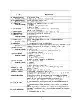
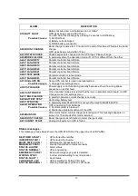
2.9 COMMAND Menu Items 

You can give immediate commands to ups by using this menu. 


Submenu items 

Function 

SOUND : ON/OFF 

Use for turn on/off beep alert sound. 
If you press ENTER key the option will change,one press ON,one press 
OFF. 
I f the OFF option is used sound alert is turn off but if a new different 
alarm is valid UPS changes de option to ON state. 

ENTER B.TEST>432 

If you press enter for 3 seconds battery test starts for 15 seconds. 
If battery test failes A6 BATT FAULT message is on panel and this 
message stays until you press ENTER key for 3 seconds. 
Numbers at the right shows the battery voltage. 
Starting of battery test time is recorded to log event menu if the test is 
successful you can see only BATTERY TEST message on log records.. 

ENTER <BYPASS> 

If you press ENTER key for 3 seconds UPS transfers load to bypass. 
If the load is on bypass in this submenu you see ENTER<INVERTER> 
message at this position if you press ENTER key for 3 seconds UPS 
transfers the load on inverter. 
In parallel modes this function disables and you see 
BYP.FUNC.DISABLE message on this submenu item. 

ENTER:MODEM INIT 

If you press ENTER key the connected modem of RS232 port is installed 
UPS sends AT command set to modem for installation. 
If the function is completed you must hear a beep sound. 
At the and of this function modem is ready to answer dial up connection. 

ENTER <BOOST> 

If you press ENTER key for 3 seconds boost charge starts. The given 
time for boost charge is 10 hours. At the end of this time UPS stops the 
boost charge. 
If the boost charge is active this submenu item changes to STOP 
BOOST> 005H 
message the 005H shows that boost charge is started 
before 5 hours. 
If the number is 10 boost charge stops. If you press ENTER key bosst 
charge stops immediately. 
Boost charge starting and boost charge end time is recorded to log event 
menu. 
If boost is active UPS beeps in each 15 seconds 

SIMULATION OFF 

The purpose of this submenu to check dry contact connections. Normally 
to check line failure contact you must turn off mains power. This is not 
necessary with this utility. 3 options are avalible. 
SIMULATION OFF simulaion mode is off 
SIM:LINE FAILURE if you press ENTER key for 3 seconds line failure 
lamp on interface board lits 
SIM:LIN.F+BT.LOW if you press enter key for 3 seconds line failure and 
battery low lamp on interface board lits  
SIM:BYPASS if you press ENTER key for 3 seconds bypass (aux) lamp 
on interface board lits. 
So you can check the connections 

ENTER EXIT 


 Enter 

 (

↵↵

 ) exit from submenu 


Goto first submenu item 


Содержание MagicLight ML-310

Страница 1: ...MagicLight ML 300 Series ML 310 ML 315 ML 320 ML 330 10 15 20 30kVA 3 Phase Input 3 Phase Output USER MANUAL...

Страница 2: ......

Страница 3: ...1 Security 20 3 1 2 Redundancy 20 3 1 3 Power Increment 20 3 2 Parallel Operation Modes 20 3 2 1 Symetric Parallel Mode 20 3 2 2 Redundant Parallel Mode 21 3 2 3 Hot Standby Mode 22 3 3 Parallel Oper...

Страница 4: ...SERVICE 36 6 1 Maintenance 36 6 2 Troubleshooting 36 6 3 Storage 36 VII REMOTE MONITORING AND CONTROL 37 7 1 Using Serial Port 37 7 2 Serial Communication Cable 37 7 3 Modem Connection 38 7 3 1 Hardwa...

Страница 5: ...e personnel The output may be energized when the unit is not connected to a mains supply Risk of electric shock hazardous live parts inside this unit are energized from the battery supply even when th...

Страница 6: ...dant On line technology with pure sine wave output PWM and IGBT technology 3 Microprocessors at each UPS Microprocessor controlled main controller board Microprocessor controlled rectifier board Micro...

Страница 7: ...vides both battery charging power and power to the inverter section BATTERY GROUP It keeps as an reserve DC power supply for the inverter in case of mains failure INVERTER It is made by utilizing the...

Страница 8: ...for battery plus and one for battery minus This circuit breaker is closed manually Also electronic controlled battery circuit breaker optional available This circuit breaker is closed manually but it...

Страница 9: ...rator or mains voltage If there is no other power supply static and mechanic by pass line input S2 and the rectifier input connections will be connect to each other See figure 1 1 During the normal op...

Страница 10: ...emale optional Dry Relay Output Contacts Figure 1 3 b 10 15 20 kVA Power Switch Location Battery Circuit Breaker Input Emergency Stop Line Failure Relay Battery Low Relay By Pass Relay BATT RS232 Comm...

Страница 11: ...B25 Female optional Dry Relay Output Contacts Figure 1 3 c 30 kVA Power Switch Location Battery Circuit Breaker Input Emergency Stop Line Failure Relay Battery Low Relay By Pass Relay RS232 Communicat...

Страница 12: ...Voltage regulation tolerance 1 Nominal Output frequency 50 Hz Output frequency tolerance line syncron 2 Output frequency tolerance free running 0 2 Efficiency 100 Load 90 Load Crest Factor 3 1 Total H...

Страница 13: ...ected to mains voltage L5 If lamp is lit mechanical bypass switch is on L6 If lamp is lit inverter feeds the load L7 If lamp is lit S4 power output switch 1 on position There are 5 function keys on fr...

Страница 14: ...3 UPS input fuses blowned A11 HIGH TEMPER Over temperature inverter or rectifier section Possible Causes 1 Overload for inverter 2 Over temperature 3 Fan failure or durty air inlets 4 Bad UPS settlin...

Страница 15: ...phase sequence or rectifier fault A40 CANT FIND PR One of parallel modes is selected but there is no parallel control board on UPS Change mode from settings menu A41 P BAL FAILURE In parallel operatio...

Страница 16: ...p system for restart user must be turn off S1 inverter input switch and turn on again WARNING STATUS Some events recorded to log event file stays on LCD PANEL but UPS continues to work these messages...

Страница 17: ...percentage OPV output voltages FREQU output frequency IPV input voltages BYP bypass source voltages BATT battery voltage and current etc SAMPLE menu selection If you want to go measures menu use UPS...

Страница 18: ...er of the UPS VERSION MC1XX Version of UPS FREQUENCY PLL XTAL Frequency generation mode ENTER EXIT Exit from submenu PASSWORD MENU password required System settings ENTER EXIT Exit from submenu SETTIN...

Страница 19: ...voltages 6 IPI 022 010 030 Input currents amperes 7 BATT 430 V 22 1 A Battery voltage and charge current 8 TEMP 030 c Cabinet inside temperature 9 CHARGE LEVEL 100 BATT CAPACI 068 Battery charge level...

Страница 20: ...on is valid 2 UPS No 001 By using PLUS and MINUS keys you can change number 0 to 3 In parallel operation select different number for each UPS If you select the same number DUBL UPS NUMBER message tell...

Страница 21: ...port is installed UPS sends AT command set to modem for installation If the function is completed you must hear a beep sound At the and of this function modem is ready to answer dial up connection 5 E...

Страница 22: ...8 ENTER UPDATE Enter update new date and time 9 ENTER EXIT Enter exit from submenu Goto first submenu item 2 11 PASSWORD Menu Items Only service personnel can use this menu the incorrect use of this m...

Страница 23: ...s to install one more UPS to the system 3 2 Parallel Operation Modes NOTE Parallel control board and some accessories are not installed to standart ML 300 series UPS but parallel operation is availabl...

Страница 24: ...d power is higher than 1 UPS power but lower than the 1UPS 2UPS total power 3 2 2 Redundant Parallel Mode At this mode if one of the UPS failes the other UPS continues to feed load Assume that UPS1 on...

Страница 25: ...nd turn on again A24 P FAILURE 17 Parallel Controller Board Failure A25 P FAILURE 18 Parallel Controller Board Failure A26 P FAILURE 19 Parallel Controller Board Failure A27 P FAILURE 20 Parallel Cont...

Страница 26: ...pass system During order the customer must give information to factory IMPORTANT NOTE Parallel system installation is much more complex from stand alone UPS installation it needs qualified sevice pers...

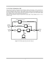
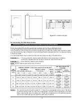
Страница 27: ...24 Figure 3 2 Parallel UPS connection...

Страница 28: ...f Condition TURN ON THE UPS By applying this procedure UPS returns to normal operation during its completely shutdown ATTENTION The following action will apply power to the load equipment 1 Open the U...

Страница 29: ...ches Into 0 OFF position WARNING Inside the UPS the following points will be on operation By pass AC input mains terminals Maintenance by pass switch Static by pass switch UPS output terminals Now you...

Страница 30: ...Open this fuses and the switches Into 0 OFF position 4 7 When Utility Power Is Interrupted When there is a utility power interrupted the L6 inverter led continuously lit also L3 battery and on the LC...

Страница 31: ...rton and the UPS 2 Carefully open the carton and take the UPS out 3 Retain the carton and packing material for future use Unit package contents User Manual Guarantee Certificate Battery cabinet and or...

Страница 32: ...AL CURRENT Amps Recommended Cable Size mm 2 BUS BAR CONNECTION STUD SIZE Input Mains With full battery Recharge Bypass output At full load Battery at min Battery Voltage Input Output Cable Termination...

Страница 33: ...ternal By Pass Supply Connections a The three white cables shown in Figure 5 2 are removed b The three phase neutral cables coming from the split by pass supply are connected to terminals U3 V3 W3 and...

Страница 34: ...nce with the battery manufacturer s recommendations In general batteries require a well ventilated clean and dry environment at reasonable temperatures to obtain efficient battery operation In general...

Страница 35: ...he racks 8 Connect the battery circuit breaker s UPS BATT and UPS BATT Ports to the battery group connection terminals at the UPS cabinet 9 Connect the shielded control cable between the UPS and the b...

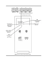
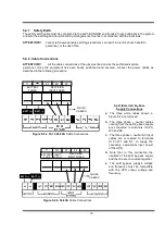
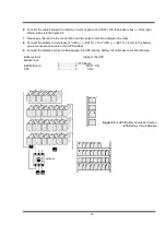
Страница 36: ...33 optional Figure 5 3 b UPS Battery Group Connection With Battery Fuse...

Страница 37: ...nections there must be a dedicated serial port ATTENTION The communication cables of this option must be shielded and must install away from the voltage cables The RS232 port at RS330 board and DB9 fe...

Страница 38: ...eople In case of a persistent failure or problem properly turn off the unit first Then review the following check list Be prepared to answer the questions before calling the service 1 Did you follow t...

Страница 39: ...ION mode Short BATTERY TEST BATTERY TEST until battery low alarm CANCEL battery test Turn off UPS output voltage immediately SHUTDOWN Turn off UPS output voltage after delay WAITING SHUTDOWN Turn off...

Страница 40: ...modem connect the UPS to the telephone line 7 3 2 Functioning Principle The remote operator by means of a PC and a modem device and using the remote connection function of the control software calls t...

Страница 41: ...RE BATTERY LOW LOAD ON BYPASS BATTERY CB input BATTERY CB output EMERGENCY STOP input ATTENTION Max 42VAC or 60VDC voltage should be applied to the dry contact outputs 7 5 Remote Monitoring Panel Remo...

Страница 42: ...he product has been subjected to physical abuse improper installation unauthorized service or modification 2 The sole responsibility of corporation under this warranty shall be limited to the repair o...

Страница 43: ...AGKK9241 05 2013...

Отзывы: