4
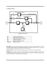
1.2 Design Concept
S1
: Inverter input power switch
S2
: Static by-pass input power switch
S3
: Maintenance by-pass power switch
S4
: UPS power out switch
S5
: Battery circuit breaker (optional)
F1-F2-F3
: Rectifier input fuses
RECTIFIER: The first conversion stage (from AC to DC) uses a 3 phase, fully controlled rectifier to convert
the incoming mains supply into a regulated DC BUS BAR. The DC BUS BAR produced by the rectifier
provides both battery charging power and power to the inverter section.
BATTERY GROUP: It keeps as an reserve DC power supply, for the inverter in case of mains failure.
INVERTER: It is made by utilizing the latest technology of power transistor (IGBT) and pulse width
modulation (PWM). Inverter converts dc bus voltage into (second conversion) an alternative voltage like line
voltage. And provides this voltage and frequency being fixed.
Inverter
Rectifier
Static By-pass
Static Transfer Switch
Maintenance By-pass
Mechanic Transfer Switch
3 Phase
Line
Input
3 Phase
Load
Output
Battery Group
S3
S2
S1
S5
S4
Figure 1-1 Block Diagram
Содержание MagicLight ML-310
Страница 2: ......
Страница 27: ...24 Figure 3 2 Parallel UPS connection...
Страница 36: ...33 optional Figure 5 3 b UPS Battery Group Connection With Battery Fuse...
Страница 43: ...AGKK9241 05 2013...

