Quanta 5
Quanta 5 Technical User Manual
59
7.2.2 On Quanta 5 device, modulation and coding
schemes are selected independently for each channel
(uplink and downlink) for both polarizations. Current
modulation for each channel is displayed in the MCS
subsection.
7.2.3 Received signal strength indicator
The RSSI indicator displays the received signal level for each channel (uplink and downlink)
and both polarizations. Available values:
-90...-80 dBm - close to the receiver sensitivity level, only the lowest modulations are
available.
-80...-60
dBm - average input range.
-60...-40
dBm - the recommended range for achieving best performance.
>-40 dBm - input signal level is too high.
Содержание Quanta 5
Страница 1: ...Quanta 5 Technical User Manual ...
Страница 37: ...Quanta 5 Quanta 5 Technical User Manual 37 ...
Страница 48: ...Quanta 5 Quanta 5 Technical User Manual 48 Figure AUX ODU LPU G Assembly Scheme ...
Страница 52: ...Quanta 5 Quanta 5 Technical User Manual 52 Figure AUX ODU LPU G Cable Gland Assembly Scheme ...
Страница 54: ...Quanta 5 Quanta 5 Technical User Manual 54 ...
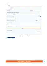
Страница 69: ...Quanta 5 Quanta 5 Technical User Manual 69 Figure Radio frontend settings 7 5 2 Air frame ...
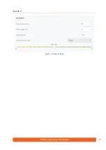
Страница 71: ...Quanta 5 Quanta 5 Technical User Manual 71 Figure Air frame settings ...
Страница 77: ...Quanta 5 Quanta 5 Technical User Manual 77 ...
Страница 98: ...Quanta 5 Quanta 5 Technical User Manual 98 9 Glossary ...
Страница 100: ...Quanta 5 Quanta 5 Technical User Manual 100 ...


