Introduction to Digital Power Conversion
XMC4000/1000 Family
PWM Generation
Application Guide
35
V1.0, 2015-01
4.11
Variable Phase-Shift
A Phase-Shift Full-Bridge (PSFB) offers the benefits of using a transformer in the DC/DC conversion
path, for level adaption or isolation.
The phase-shift of two PWM signals to the bridge control inputs converts the bridge DC rail voltage
proportionally to a transformable AC-voltage, with a defined ratio (See also
).
The target DC output voltage is rectified and LC-filtered after the secondary coils of the transformer.
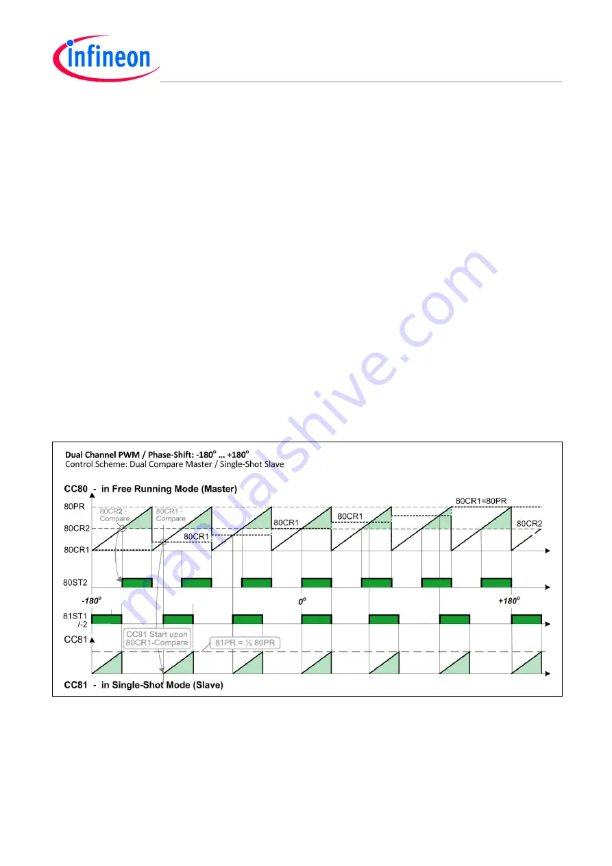
PWM Phase-Shift by Master-Slave Timer Configuration
The PSFB phase-shift control signal-pair should be generated by one master timer that can guarantee
a fixed PWM pulse rate, and one slave timer in single-shot mode for the phase-shifted PWM pulses,
which should be controlled by the master timer as follows:
CC80-Channel1 controls the phase-shift by variable compare events that starts the slave PWM
cycle as single shots
CC80-Channel2 compare events generate the free-running master PWM
Other setups might cause issues on big phase-shifts.
Note:
1. The suggested timer configuration allows for the highest possible phase-shift dynamic (-180
o
to +180
o
).
However, in most practical power conversion use cases with PSFB, 180
o
dynamic range is enough.
2. It is possible to vary the Duty-Cycles of each signal in the PWM phase-shift pair to any extent (Not shown
here).
Figure 24
PWM
– Variable Phase-Shift by Master-Slave Timer Configuration


