AP29000
Connecting C166 and C500 Microcontroller to CAN
The Infineon CAN Devices C167CR, C515C and SAE 81C90/91
Application Note
25
V 1.0, 2004-02
•
The Bit Timing Logic (BTL) monitors the busline input CAN_RxD and handles the
busline related bit timing according to the CAN protocol. The BTL synchronises on a
recessive to dominant busline transition at Start of Frame (hard synchronisation)
and on any further recessive to dominant busline transition, if the CAN controller
itself does not transmit a dominant bit (resynchronisation). The BTL also provides
programmable time segments to compensate for the propagation delay time and for
phase shifts and to define the position of the Sample Point in the bit time. The
programming of the BTL depends on the baudrate and on external physical delay
times.
•
The
Intelligent Memory
(CAM/RAM Array) provides storage for up to 15 message
objects of maximum 8 data bytes length. Each of these objects has a unique
identifier and its own set of control and status bits. After the initial configuration, the
Intelligent Memory can handle the reception and transmission of data without further
CPU actions.
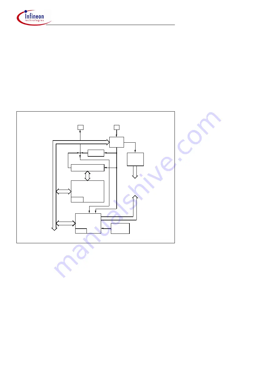
Figure 7
Block Diagram of the CAN Controller on the C167CR / C515C
to internal Bus
Error
Clocks
Messages
Control
Handlers
Messages
( to all )
CRC
BTL - Configuration
TX/RX Shift Register
Timing
Generator
Register
Intelligent
Memory
Interrupt
Status
Register
Transmit
Receive
Control
Bit
Timing
Logic
Pin
Pin
Gen./Check
Bit
Stream
Processor
Management
Logic


