36
• DOK-POWER*-TVD*1.3****-ANW1-EN-E1,44 • 02.97
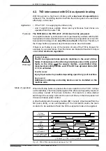
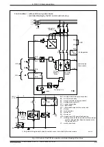
4.2. TVD interconnect with DC bus dynamic braking
With this variant, a high level of safety with a low level of expenditure is
achieved. The monitoring devices built into the drive system are used most
effectively, in this case:
• if the TVD 1.3 is supplying feed drives only
• and if asynchronous spindle drives and synchronous feed drives are
operated from the same TVD.
The NCB link on the TVD (X3/1 - X3/2) must not be jumpered.
It is posible to brake synchronous motors (permanently excited) with the DC
bus dynamic brakes whether the drive electronics are operational or not. DC
bus dynamic braking occurs only if there is a fault in the drive. Therefore, if
the E-stop button is pressed, asynchronous drives are also braked.
If there is an E-stop or one of the monitor circuits of the TVD is tripped, for
example, by a power failure, then the drives are braked at maximum torque
under drive electronic regulation.
4. TVD 1.3 Interconnections
Source of danger:
The DC bus dynamic brake protects machines in the event of drive
failure. It alone does not function to protect personnel. In the event of
faults in the drive and the supply module, uncontrolled drive
movements are still possible even if the DC bus dynamic brake (X2/
2 = 0) is activated.
Possible cauess:
Injury to personnel is possible depending upon the type of machine.
How to avoid:
Additional monitoring and safety devices can be installed on the
machine side.
Warning!
When the E-stop button is pressed, the main contactor in the TVD 1.3 drops
out immediately. The drive enable signal of the drives is dropped by means of
an auxiliary contact of the main contactor. This leads to a drive-internal
switching of the velocity command to zero in all drives in the drive packet. All
drives are braked under control.
A drive fault signal to the supply module (Bb1 contact), a fault signal from the
NC (servo fault), or an overtravelling of the limit switch cause the main
contactor to be switched off and the DC bus dynamic brake to be applied.
Mode of operation
DC bus
short-circuit
OFF
ON
K1
(X5/3-4)
DC bus
voltage
UD contact
Drive enable signal
from control unit
t
1
≥
200 ms; t
2
= 1.25 ... 1,4 s; t
3
≥
40 ms
t
3
t
2
t
2
t
1
t
1
t
1
SVTVDmZW
Fig. 4.2: Path of the signal when powering up the TVD
Features
Application
Содержание TVD 1.3
Страница 6: ...6 DOK POWER TVD 1 3 ANW1 EN E1 44 02 97 Em pty page ...
Страница 72: ...Indramat ...

