37
• DOK-POWER*-TVD*1.3****-ANW1-EN-E1,44 • 02.97
4. TVD 1.3 Interconnections
Netzschütz
Haltebremse
Achsendlage
Verriegelung Schutz-
türe
Q10
Q1
ϑ
1
2
Y1
4
3
+24V
+/- 10%
K1
RF
K4
Bb
K4
X9/L+
X9/L-
X3/1
X3/2
RF
drive
module
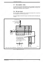
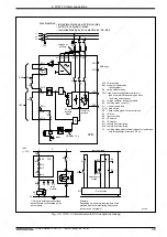
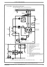
Bb1 = supply module ready (drive system)
Bb = drive module ready
CNC = lag error message from the control unit
(use only contact that does not open
when E-stop switch opens)
K1 = mains contactor in supply module
K4 =holding brake control 1)
Q1 = power supply fuse
Q10 = main switch
RF = drive enable signal of the control unit
S1 = E-stop
S2 = axis end stop
S4 = power off
S5 = power on
Y1 = holding brake for feed axis with electrical release;
note the release delay! Speed command value
100 ms after RF on
Y2 = safety door locks
0V
SS1TVR
• with DC bus dynamic braking
• regulated braking by drive electronics with an E-stop
L1
L2
L3
K1
Y2
U
U
U
2U1 2V1 2W1
1U1 1V1 1W1
X2/1
Bb1
X2/2
X2/3
S1
S4
X2/4
X2/5
S5
K1
X2/6
On delay 1.4 s
&
converter
release
power supply
drive module
K1
DC bus
dynamic
braking
NCB open
X4/1
S2
TVD
TVD
X5/1
X5/2
X4/2
CNC
X5/3
X5/4
1)
TVD
1)
1) Only with holding brakes for feed drives that are not controlled by the drive module.
Functionalities:
1
bridged at
delivery
ready
ON
OFF
ZKS
RF
RF
X4/3
UD
X4/4
Fig. 4.3: Controlling the TVD 1.3 with DC bus dynamic brake
Содержание TVD 1.3
Страница 6: ...6 DOK POWER TVD 1 3 ANW1 EN E1 44 02 97 Em pty page ...
Страница 72: ...Indramat ...

