IPX Manual RB01
CAUTION NOTE
1.
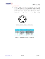
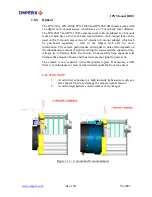
Old IPX and MDC camera shipped prior to March 1, 2005, come with
a power cable which terminates in a HIROSE plug #HR10A-10R-10P,
tail cable ending with 4 pin interface connector
and have a small pig-
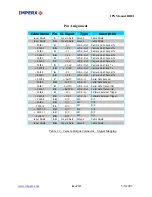
for the external trigger input and strobe output. The I/O interface
connector is shown in Figure 1.7, and the corresponding pin mapping
in Table 1.5b.
1
3
2
4
Figure 1.7. I/O Cable Interface – Old Connector.
Pin
Signal
Description
1
Trigger In -
External Trigger Input
2
Trigger In +
External Trigger Input
3
Strobe Out +
Strobe Light Sync Pulse
4
Strobe Out -
Strobe Light Sync Pulse
Table 1.5b – I/O Interface Connector - Pin Mapping
www.imperx.com
27
of
137
5/6/2005
Содержание IPX CAMERA SERIES
Страница 2: ...IPX Manual RB01 www imperx com Revision History RB01 05 03 05 P Dinev First Release 2 of 137 5 6 2005...
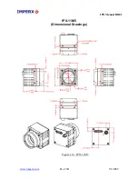
Страница 30: ...IPX Manual RB01 IPX 1M48 Dimensional Drawings Figure 1 11 IPX 1M48 www imperx com 30 of 137 5 6 2005...
Страница 32: ...IPX Manual RB01 IPX 4M15 Dimensional Drawings Figure 1 13 IPX 4M15 www imperx com 32 of 137 5 6 2005...
Страница 33: ...IPX Manual RB01 IPX 11M5 Dimensional Drawings Figure 1 14 IPX 11M5 www imperx com 33 of 137 5 6 2005...
Страница 35: ...IPX Manual RB01 Figure 1 16 IPX VGA 2M30 H 4M15 MDC1600 1920 2048 Bottom View www imperx com 35 of 137 5 6 2005...
Страница 36: ...IPX Manual RB01 Figure 1 17 IPX 1M48 and MDC1004 Top View www imperx com 36 of 137 5 6 2005...
Страница 37: ...IPX Manual RB01 Figure 1 18 IPX 1M48 and MDC1004 Bottom View www imperx com 37 of 137 5 6 2005...


