IPX Manual RB01
1.4
CAMERA CONNECTIVITY
1.4.1 General
Description
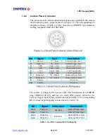
The interface between the IPX camera and outside equipment is done via
two connectors and one LED, located on the back panel of the camera –
Figure 1.4a.
t – standard base Camera Link provides data, sync,
al interface.
4.
Serial Number – shows camera model and serial number.
1.
Camera outpu
control, and seri
2.
Power Connector – provides power and I/O interface.
3.
Status LED – indicates the status of the camera – refer to Status LED
section.
1
2
3
4
1
4
2
3
1
4
2
3
IPX-VGA / 2M30 / 2M30H / 11M5
IPX-1M48
IPX-4M15
Figure 1.4a – New IPX Camera Back Panel (sold after March 1, 2005)
CAUTION NOTE
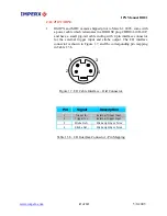
1. Old IMPX and MDC cameras sold prior to March 1, 2005 have
back panel shown on Figure 1.4b.
www.imperx.com
22
of
137
5/6/2005
Содержание IPX CAMERA SERIES
Страница 2: ...IPX Manual RB01 www imperx com Revision History RB01 05 03 05 P Dinev First Release 2 of 137 5 6 2005...
Страница 30: ...IPX Manual RB01 IPX 1M48 Dimensional Drawings Figure 1 11 IPX 1M48 www imperx com 30 of 137 5 6 2005...
Страница 32: ...IPX Manual RB01 IPX 4M15 Dimensional Drawings Figure 1 13 IPX 4M15 www imperx com 32 of 137 5 6 2005...
Страница 33: ...IPX Manual RB01 IPX 11M5 Dimensional Drawings Figure 1 14 IPX 11M5 www imperx com 33 of 137 5 6 2005...
Страница 35: ...IPX Manual RB01 Figure 1 16 IPX VGA 2M30 H 4M15 MDC1600 1920 2048 Bottom View www imperx com 35 of 137 5 6 2005...
Страница 36: ...IPX Manual RB01 Figure 1 17 IPX 1M48 and MDC1004 Top View www imperx com 36 of 137 5 6 2005...
Страница 37: ...IPX Manual RB01 Figure 1 18 IPX 1M48 and MDC1004 Bottom View www imperx com 37 of 137 5 6 2005...

