IPX Manual RB01
2.5
EXTERNAL TRIGGER
In the
trigge
There
hardw
In ha
the c
optic
signa
exter
volta
signa
TRIG
To li
maxi
uration
does not affec
e
determined by
u
ger
pulse is 100 microseconds. There are no restrictions for the maximum pulse
duration, but it is recommended that the trigger pulse is kept as short as possible,
especially if a series of pulses are used.
In software triggering mode the camera receives the trigger signal coming from
the frame grabber via camera control signal CC1. In this mode the integration
time for the first frame is determined by the duration of the actual CC1 trigger
pulse.
normal mode of operation, the camera is free running. Using the external
r mode allows the camera to be synchronized to an external timing pulse.
are two general modes available for external triggering – software and
are.
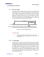
rdware triggering mode the camera receives the trigger signal coming from
onnector located on the back of the camera. The hardware trigger input is
ally isolated from the rest of the camera hardware - Figure 2.31. The input
ls “+ TRIGGER IN” and “– TRIGGER IN” are used to connect to an
nal trigger source. On the edge of the external pulse which creates a positive
ge difference between “+ TRIGGER IN” and “– TRIGGER IN”, a trigger
l is sent to the camera. The voltage difference between the trigger inputs “+
GER IN” and “– TRIGGER IN” must be positive between 3.3 and 5.0 volts.
mit the input current a 300 ohm internal resistor is used, but the total
mum current MUST NOT exceed 25 mA. The actual trigger pulse d
t the integration time. The integration time for th first frame is
the Pre-Exposure register. The minim m duration of the trig
TO CAMERA
+ TRIGGER IN
- TRIGGER IN
R1
300
25 mA MAX
C A M E R A
Hardware Trigger Electrical Connection
Figure 2.31 -
2.5.1
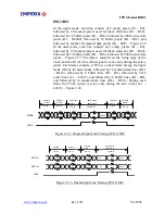
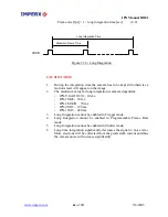
When the standard triggering mode is enabled, the camera idles and waits
for a trigger signal. Upon receiving the external trigger signal, the camera
clears the horizontal and vertical registers, sends one 5 microseconds shutter
pulse to clear the pixels and starts integration. The exposure time for the
Standard Triggering - Programmable Exposure
www.imperx.com
67
of
137
5/6/2005
Содержание IPX CAMERA SERIES
Страница 2: ...IPX Manual RB01 www imperx com Revision History RB01 05 03 05 P Dinev First Release 2 of 137 5 6 2005...
Страница 30: ...IPX Manual RB01 IPX 1M48 Dimensional Drawings Figure 1 11 IPX 1M48 www imperx com 30 of 137 5 6 2005...
Страница 32: ...IPX Manual RB01 IPX 4M15 Dimensional Drawings Figure 1 13 IPX 4M15 www imperx com 32 of 137 5 6 2005...
Страница 33: ...IPX Manual RB01 IPX 11M5 Dimensional Drawings Figure 1 14 IPX 11M5 www imperx com 33 of 137 5 6 2005...
Страница 35: ...IPX Manual RB01 Figure 1 16 IPX VGA 2M30 H 4M15 MDC1600 1920 2048 Bottom View www imperx com 35 of 137 5 6 2005...
Страница 36: ...IPX Manual RB01 Figure 1 17 IPX 1M48 and MDC1004 Top View www imperx com 36 of 137 5 6 2005...
Страница 37: ...IPX Manual RB01 Figure 1 18 IPX 1M48 and MDC1004 Bottom View www imperx com 37 of 137 5 6 2005...

