IMO TP40A Скачать руководство пользователя страница 17

When OUT1 is non-contact voltage output or DC current output, between OUT1 and communication 
and between OUT1 and SV2 are non-isolated and isolation test 

must not

 be carried out between them. 


Isolation resistance

: 10M   or greater at 500V DC 

Dielectric strength 

: 1.5kV AC for 1minute between input terminal and power terminal 


1.5kV AC for 1minute between output terminal and power terminal


Supply voltage


: 100 to 240V AC    50/60Hz, 24V AC/DC    50/60Hz 


Allowable voltage fluctuation 

100 to 240V AC: 85 to 264V, AC 24V AC/DC: 20 to 28V AC/DC 

Power consumption

: Approx. 8VA 

Ambient temperature

: 0 to 50


(32 to 122 ) 

Ambient humidity

    : 35 to 85%RH (no condensation) 


Weight  

: Approx. 200

g


External dimension

: 48 x 48 x 95mm (W x H x D) 

Material  

: Flame resistant resin (Case) 

Color

: Light gray (Case) 

Attached functions

 : 

[Setting value lock], [Sensor correction], [Auto/manual control switching],


[Input burnout indication

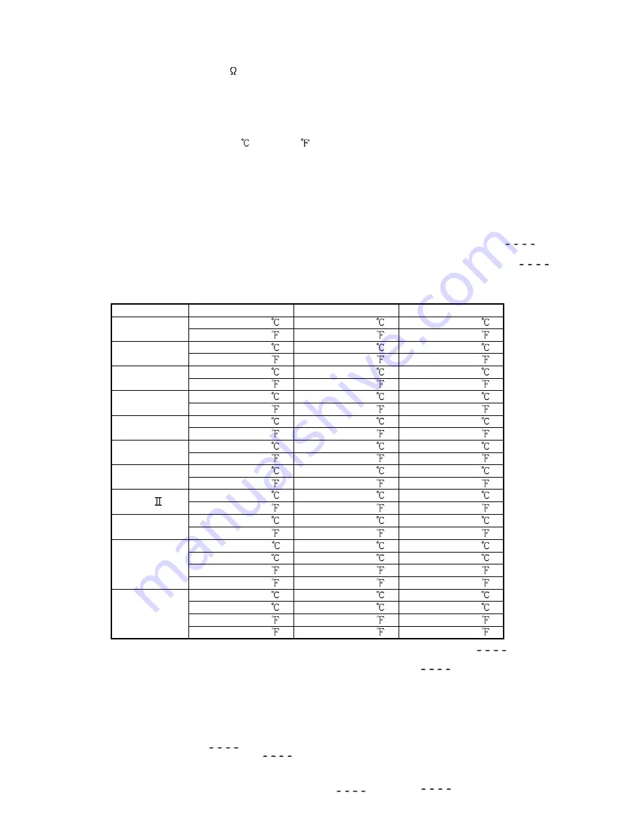
Thermocouple and RTD inputs 

If the input value exceeds the Indication range high limit value, the PV display blinks “

”,  

and if the input value exceeds the Indication range low limit value, the PV display blinks “

”. 

If the input value exceeds the Control range, OUT1 and OUT2 are turned off (for DC current 

output type, OUT1 low limit value and OUT2 low limit value)
(However, for manual control, it outputs the preset manipulated variable

Input Input 

range 

Indication range 

Control range 

   –199.9 to 400.0  

   –199.9 to 450.0  

   –205.0 to 450.0  

K T 

   –199.9 to 750.0  

   –199.9 to 850.0  

   –209.0 to 850.0  

    –200 to 1370  

    –250 to 1420  

    –250 to 1420  

    –320 to 2500  

    –370 to 2550  

    –370 to 2550  

    –200 to 1000  

    –250 to 1050  

    –250 to 1050  

    –320 to 1800  

    –370 to 1850  

    –370 to 1850  

        0 to 1760  

      –50 to 1810  

      –50 to 1810  

R S 

        0 to 3200  

      –50 to 3250  

      –50 to 3250  

        0 to 1820  

      –50 to 1870  

      –50 to 1870  

        0 to 3300  

      –50 to 3350  

      –50 to 3350  

     –200 to 800  

     –250 to 850  

     –250 to 850  

    –320 to 1500  

    –370 to 1550  

    –370 to 1550  

    –200 to 1300  

    –250 to 1350  

    –250 to 1350  

    –320 to 2300  

    –370 to 2350  

    –370 to 2350  

        0 to 1390  

      –50 to 1440  

      –50 to 1440  

PL-  

        0 to 2500  

      –50 to 2550  

      –50 to 2550  

        0 to 2315  

      –50 to 2365  

      –50 to 2365  

C(W/Re5-26) 

        0 to 4200  

      –50 to 4250  

      –50 to 4250  

–199.9 to 850.0  

  –199.9 to 900.0  

  –210.0 to 900.0  

 –200 to 850  

 –210 to 900  


–210 to 900  

  –199.9 to 999.9  

  –199.9 to 999.9  

 –211.0 to 1099.9  

Pt100 

    –300 to 1500  

    –318 to 1600  

    –318 to 1600  

  –199.9 to 500.0  

  –199.9 to 550.0  

  –206.0 to 550.0  


–200 to 500  


–206 to 550  


–206 to 550  

  –199.9 to 900.0  

  –199.9 to 999.9  

  –211.0 to 999.9  

JPt100 


–300 to 900  


–312 to 1000  


–312 to 1000  

DC current and voltage inputs 

(4 to 20mA DC, 0 to 20mA DC, 0 to 1V DC, 0 to 5V DC, 1 to 5V DC, 0 to 10V DC)


If input value exceeds Indication range high limit value, PV display blinks “

, and if input 

value exceeds the Indication low limit range, the PV display blinks “

”. 

If input value exceeds the Control range, OUT1 and OUT2 are turned ON or OFF, depending on  

which has been selected 

in 

the [Output status selection when input burnout] (for DC current output 

type, OUT1 high or low limit value, OUT2 high or low limit value). However, for manual control, it  

outputs the preset manipulated variable. 


Indication range

: [Scaling low limit value – Scaling span x 1%] to [Scaling high limit value 

+Scaling span x 10%] 

(If the input value exceeds the range –1999 to 9999, the PV display blinks 


” or “

”) 

Control range


: [Scaling low limit value – Scaling span x 1%] to [Scaling high limit value 


+Scaling span x 10%] 

DC input burnout

: When DC input is burnt out, PV display blinks “

” for 4 to 20mA DC 


and 1 to 5V DC inputs, and “

” for 0 to 1V DC input. 

17 

Содержание TP40A

Страница 1: ...it might deform or tarnish the unit As the display section is vulnerable do not strike or scratch it with a hard object Any unauthorized transfer or copying of this document in part or in whole is pr...

Страница 2: ...key the setting value or selected value can be registered 14 OUT OFF key The control output ON OFF function or Auto Manual control function can be switched To cancel the control output ON OFF function...

Страница 3: ...unting Mount the controller vertically to fulfill the Dust proof Drip proof specification IP66 Mountable panel thickness Within 1 to 15mm Insert the controller from the front side of the panel Attach...

Страница 4: ...uilt in power switch circuit breaker or fuse Therefore it is necessary to install them in the circuit near the external controller Recommended fuse Time lag fuse rated voltage 250V AC rated current 2A...

Страница 5: ...he input range high limit value is indicated on the SV display for approximately 3 seconds Table 5 1 If any other value is set during the scaling high limit setting the set value is indicated on the S...

Страница 6: ...OUT1 high limit setting A1 action delayed timer setting OUT1 proportional cycle setting Data transfer rate selection OUT1 low limit setting A2 action delayed timer setting OUT2 proportional cycle sett...

Страница 7: ...Not available when OUT1 is ON OFF action Auto reset can be performed when PD action I 0 Setting range 0 to 1000 seconds 200 seconds Derivative time setting Sets derivative time for OUT1 Setting the va...

Страница 8: ...ds on the designation When Lock 1 or Lock 2 is designated PID Auto tuning and Auto reset cannot be carried out Unlock Unlock All setting values can be changed Lock 1 None of the setting values can be...

Страница 9: ...0 4 to 20mA 1999 to 9999 0 to 20mA 1999 to 9999 0 to 1V 1999 to 9999 0 to 5V 1999 to 9999 1 to 5V 1999 to 9999 0 to 10V 1999 to 9999 K 320 to 2500 199 9 to 750 0 J 320 to 1800 R 0 to 3200 S 0 to 3200...

Страница 10: ...to 100 0 or 1 to 1000 0 OUT2 ON OFF action hysteresis setting Sets ON OFF action hysteresis for OUT2 Available only when the option DT is added Setting range 0 1 to 100 0 or 1 to 1000 1 0 A1 action se...

Страница 11: ...is overscale or underscale Available only for DC current output type with DC inputs Output OFF Output ON Output OFF OUT OFF key function selection Selects whether OUT OFF key is used for control outp...

Страница 12: ...of the unused instrument of the plural units OFF even if the power to the instrument is supplied is indicated on the PV display while the function is working Once the control output OFF function is en...

Страница 13: ...dby High Low limit alarm with standby Low limit alarm with standby OFF ON A1 hysteresis OFF ON SV setting OFF ON A1 hysteresis OFF ON OFF ON OFF ON OFF ON OFF ON OFF ON Alarm action Alarm action Alarm...

Страница 14: ...or OFF unlit Represents Heating control action Represents Cooling control action 7 6 OUT2 Heating Cooling control action When setting Dead band Changes continuously according to deviation Non contact...

Страница 15: ...the temperature rises When AT bias is set to 20 fluctuation is applied at the temperature 20 lower than the setting value 15 1 2 3 4 Temperature Setting value 1 Calculating PID constant 2 PID constant...

Страница 16: ...reater Allowable input voltage 15V or less Allowable signal source resistance 100 or less OUT1 output Relay contact 1a Control capacity 3A 250V AC resistive load 1A 250V AC inductive load cos 0 4 Elec...

Страница 17: ...370 to 1850 370 to 1850 0 to 1760 50 to 1810 50 to 1810 R S 0 to 3200 50 to 3250 50 to 3250 0 to 1820 50 to 1870 50 to 1870 B 0 to 3300 50 to 3350 50 to 3350 200 to 800 250 to 850 250 to 850 E 320 to...

Страница 18: ...breaking status on the loop such as heater burnout sensor burnout or actuator trouble The output terminals will be common if the options W and A2 are applied together Setting range Loop break alarm ac...

Страница 19: ...e the function is blinking on the PV display Thermocouple RTD or DC voltage 0 to 1V DC is burnt out Change each sensor How to check sensor burnout Thermocouple If the input terminal of the instrument...

Страница 20: ...nterference or noise away from the controller The PV display is indicating Internal memory is defective Contact our agency or us 10 2 Key operation Problem Presumed cause and solution Unable to set th...

Отзывы: