22
English
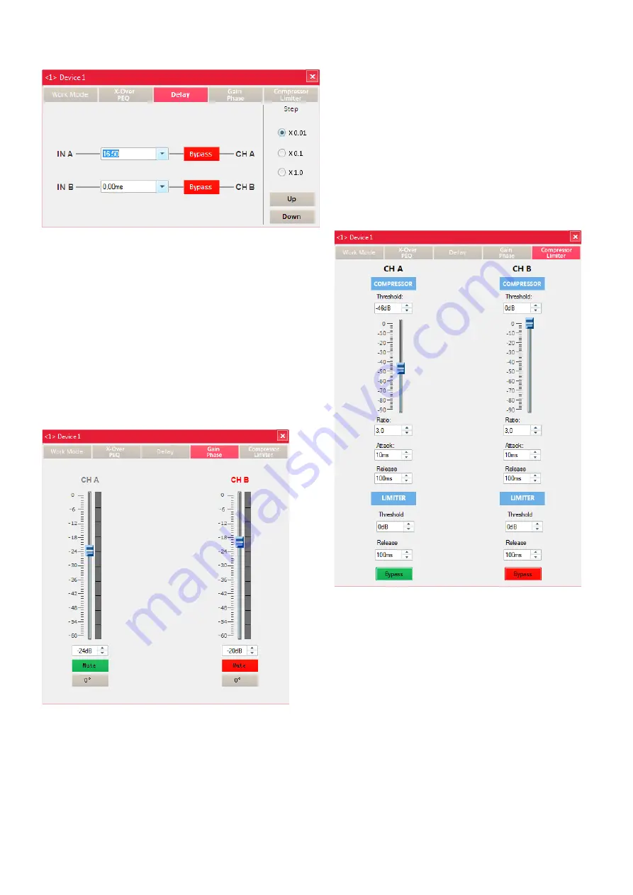
7.4.3 View “Delay”
In this view, the signal delay (e . g . to compensate different distances
between speakers and audience) can be set (cf . chapter 6 .3 .5):
Fig. 15 View “Delay”
Either enter a numeric value in the field or use the buttons UP and
DOWN to increase or reduce the current value in steps . The increment
of the steps is defined by the value selected under “Step” .
Use the small triangle next to the input field to change the unit
from milliseconds to centimetres or feet so that it is possible to enter
the delay as a distance . When you enter a distance, the calculation of
the delay time will be based on a sound speed of 340 m/s .
Use the button BYPASS to activate or deactivate the delay:
Red:
deactivation of the delay
Green:
activation of the delay
7.4.4 View “Gain, Phase”
In this view, the attenuation of the input signals, i . e . the volume of
the channel, can be set (cf . chapter 6) . In addition, it is possible to
invert the signal (phase reversal, cf . chapter 6 .3 .6) .
Fig. 16 View “Gain, Phase”
– Use the sliders to set the value desired or enter the value in the fields .
– Use to button “Mute” to mute and unmute a channel .
– Use the button “0°”/”180°” to invert the signal of a channel .
A colour bar next to the sliders indicates the input level of the signals .
7.4.5 View “Compressor, Limiter”
In this view, compression and level limitation settings can be made . The
compressor reduces the dynamic range and attenuates the level above
an adjustable threshold . This will be necessary when the dynamic range
of the audio signal is higher than allowed by the amplifier system or
the listening situation (e . g . in case of background music) . It is also
possible to reduce level differences (e . g . for changing microphone
distances) or to attenuate signal peaks in order to allow a higher gain
setting and thus to obtain a higher average volume .
With the limiter, the signal can be quickly limited to an adjusted
level . This will protect the speakers, for example, against overload .
The limiter works in a similar way as the compressor described above .
However, while the compressor still allows an increase of the output
level above the threshold value, depending on the compression rate
defined, the threshold value of the limiter defines the definite upper
limit of the output signal (compression ratio = ∞ : 1) .
Fig. 17 View “Compressor, Limiter”
The upper part of the view provides the settings for the compressor
(cf . chapter 6 .3 .7), the lower part “LIMITER” provides the settings for
the limiter (cf . chapter 6 .3 .8) . To activate or deactivate both settings
at the same time, use the appropriate button “Bypass” .
Parameters for the
compressor
:
Threshold: threshold value in dBV (0 dB = 1 V); the gain will be atten-
uated when the signal level has exceeded this value
Ratio:
compression ratio
with a compression rate of 10, for example, the output
level above the threshold value will increase by only 2 dB
when the input level increases by 20 dB
Attack:
attack time
Release:
release time, i . e . the time the gain takes to reach its
original value after the signal level has fallen below the
threshold value
This value cannot be smaller than the “Attack” value .
Содержание 25.9510
Страница 47: ...47...


