IKA STARVISC 200-2.5 control Скачать руководство пользователя страница 17

17

Operating Mode:

Operating Mode A:

In this operating mode, the set speed is not saved when the current 
run comes to an end or the device is switched off.

Operating Mode B:

In this operating mode, the set speed is saved when the current 
run comes to an end or the device is switched off, and the value 
can be changed.

Operating mode C:

In this operating mode, the set speed is saved when the current 
run comes to an end or the device is switched off, and the value 
cannot be changed.

Display:

In the “Display“ menu the user can specify what information will be 
displayed on the main screen.

Note: 

If the ”Torque”option is activated, by pressing the ”Back“ 

button the user can reset the current torque to 0 Ncm as a refer-
ence value. At the same time the Δ appears in front of the Ncm unit.

Programs:

Under menu "Programs", 5 user-defined speed (rpm)-time profiles 
can be created. In addition, the user could define the intermittent 
mode is activated or not in the programs. 
If the intermittent mode is activated, the run time/stop time value 
from "Intermittent Mode" setting will be taken. 

Note: If user need to activate the intermittent mode in one segment 
of a program, he should set the "Run time/Stop time" in menu op-
tion "Interval", meanwhile activate the "Run/Stop" function in menu 
option "Intermittent Mode" (see section "Stirring"). 
Once a programs has been selected, the following options are available.

Start:

 Start the selected program upon request.

When the selected program is started by pressing on menu option 
"Start" with rotary/push knob, screen reminds the user to confirm 
the program control. Press "OK" with rotary/push knob to start the 
program control.

Edit: 

Edit the selected program parameters.

Start to edit the selected program parameters by pressing on menu 
option "Edit" with rotary/push knob. The user can edit, delete or 
insert one selected program segment in the program. 
When user edits the program time for at least one segment, tick (

for respective program will appear.

Delete: 

Deletes the selected program.

If a selected program is deleted by pressing on menu option "Delete" 
with rotary/push knob, all the program parameters will be emptied. 
The tick (

) disappears.

Details for editing the program:

When a program is being edited, following screen appears.

PROGRAM 1

Seg
No

.

rpm

Time
hh:mm

Interm.
Mode

Edit

Delete

Insert

1

2

3

4

5


0

00:00


 No

In this program, user can define up to 5 seg-
ments. The selected segment is highlighted. 
Then, the user can edit, delete or insert a 
segment in this program. 
When the "Back" button is pressed after ed-
iting, the program is save automatically.

Edit:

When the highlighted "edit" symbol appear on the right top of 
the screen, the user could change the speed (rpm), time value or 
intermittent mode setting.

Note: 

The speed (rpm) value can be changed during the speed 

limit range of the device. The time can be set from 1 minute to 
10 hours. 

Delete:

When delete a highlighted segment, the settings will be emptied. The  
section jump to next segment.

Insert:

With the insert option, a new segment will be insert below the 
selected segment. The default settings for the new segment are as 
following:
rpm: 0
Time (hh:mm): 00:01
Intermittent Mode: No

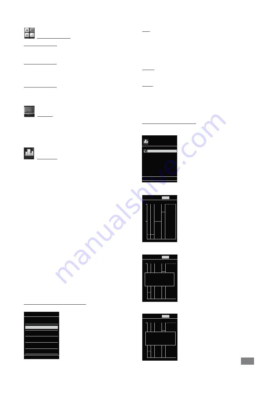
View the program in graph:

After a program is being edited, press the "Back" button to save the set-
tings. Press the "Back" button again, the screen back to follow screen. 

If no button or knob is pressed or turned for 5 seconds, pictorially 
respective program will be shown.

rpm

250

500

PROGRAM 1 

Detail

Programs

Start

Edit

Delete

Program 1

Program 2

Program 3

Program 4

Program 5

rpm

250

500

Seg No.: 

1

rpm:

100

Time (hh:mm:ss): 

00:10:00

Interm. Mode: 

Yes

PROGRAM 1 

Detail

rpm

250

500

Seg No.: 

2

rpm:

200

Time (hh:mm:ss): 

00:10:00

Interm. Mode: 

No

PROGRAM 1 

Detail

Press the rotary/push knob on option "Detail", the detailed settings 
of every segment can be seen.

Turn the rotary/push knob, the details screen of every segment can 
be switched.

Содержание STARVISC 200-2.5 control

Страница 1: ...20000015716 IKA STARVISC 200 2 5 control STARVISC 200 2 5 control_062018...

Страница 2: ...e setup Dangerous parts Fig 3 1 2 3 4 Fig 2 Fig 4 H I J G G K L M Fig 1 A J I H G F E STARVISC 200 2 5 control station Wireless Controller WiCo Q B M O N C L K P D Fig 7 Fig 5 Fig 6 T U Q S U X I G Z...

Страница 3: ...he equipment This device complies with Part 15 of the FCC rules subject to the following two conditions 1 This device may not cause harmful interference and 2 This device must accept all interference...

Страница 4: ...r safety can not be ensured simply with design requirements on the part of the product For this reason it may become necessary for users to take other precautionary safety measures For example glass d...

Страница 5: ...is fully discharged the only means of switching the station off are the safe STOP and the off switch Please note the following safety in structions for the battery pack RB 1 re chargeable battery Kee...

Страница 6: ...ce is operated improperly or contrary to the manufac ture s speci cations if the device or the printed circuit board are modi ed by third parties Drive The rotary knob B see Fig 1 of the WiCo allows t...

Страница 7: ...verhead stirrer must be secured to a stable stand e g R 2722 or R 2723 with a cross sleeve e g R 270 The stirring vessel must always be securely xed for safety reasons You must also ensure that the mo...

Страница 8: ...emperature sensor cable should be plugged into the appropriate port after the covers have been removed as shown in Fig 6 Once the device has been connected to the PC using the USB data cable it will t...

Страница 9: ...to search for the WiCo A beep signal will be audible even if the WiCo is switched off Speed setting You can use the rotary knob B see Fig 1 to pre set the required speed before you start the device I...

Страница 10: ...station is communicating via a USB cable The symbol no longer appears if no USB cable is being used for communicating with the station Home This symbol means that the WiCo is connected to the station...

Страница 11: ...the Menu button N Select the menu by turning the rotary push knob B to the right or left to select the desired menu or sub menu which can then be selected by pressing the rotary push knob Press or tu...

Страница 12: ...ate Info Black White Standard Mode Battery Mode Volume Key Tone Device Name Remote Control Bluetooth WiCo Other Stirring Safety Software Max Speed Max Torque Interval Run Time Out Station Version Inte...

Страница 13: ...for stirring tasks which require metering and feeding additives Torque Display The Torque Display menu allows the user to specify that the torque is shown in the display A tick shows that the option...

Страница 14: ...suring error max 12 Sample volume 1500 ml Necessary beaker HF 3000 DIN 12332 3000 ml low shape 1500 ml 150 mm 210 mm 10 mm R 1302 Measuring condition Paddle stirrer R 1375 Measuring condition Anchor s...

Страница 15: ...nd the stirring elements appertaining thereto based upon the physical laws and taking into account the smallest error square out of more than 20 measuring values with Newtonian calibration oils at 22...

Страница 16: ...mer is interrupted 4 Select the stirrer tool Select the proper the stirrer tool R 1302 HV Press on OK to confirm the setting Viskosit t R hrer OK R 1345 HV Viskosit t R hrer OK R 1302 HV Viskosit t R...

Страница 17: ...gram segment in the program When user edits the program time for at least one segment tick for respective program will appear Delete Deletes the selected program If a selected program is deleted by pr...

Страница 18: ...ode Edit Delete Insert 1 2 3 4 5 150 0 00 10 00 00 Yes No Programs Start Edit Delete Program 1 Program 2 Program 3 Program 4 Program 5 PROGRAM 1 Seg No rpm Time hh mm Interm Mode 1 2 3 4 5 0 00 00 No...

Страница 19: ...ou to select the desired lan guage by turning and pressing the rotary push knob B A tick indicates the language that is set for the system Units The Units option allows you to select the desired unit...

Страница 20: ...at the computer s request Command syntax and format The following applies to the command set Commands are generally sent from the computer Master to the stirrer machine Slave The stirrer machine sends...

Страница 21: ...to the computer A USB micro B USB A 9 pin RS 232 9 pin RS 232 or micro B A USB micro B USB A micro B USB A USB A or A 9 pin RS 232 9 pin RS 232 USB micro B USB A micro B USB A USB 2 0 cable micro A mi...

Страница 22: ...ou require servicing return the device in its original packag ing Storage packaging is not sufficient Please also use suitable transport packaging Warranty In accordance with IKA warranty conditions t...

Страница 23: ...tirrer n 1000 R 1342 Propeller stirrer 2000 R 1345 Propeller stirrer n 800 R 1381 Propeller stirrer 2000 R 1382 Propeller stirrer 2000 R 1385 Propeller stirrer 800 R 1388 Propeller stirrer 400 R 1389...

Страница 24: ...e VAC 230 10 115 10 100 10 Frequency Hz 50 60 Max input power W 130 Max output power at stirring shaft W 84 IP code according to EN 60529 IP 40 Protection class I Excess voltage category II Contaminat...

Страница 25: ...W x D x H mm 71 x 74 x 151 Weight kg 0 28 Ambient temperature C 5 40 Ambient humidity relative 80 IP code according to EN 60529 IP 40 Interface USB Battery pack Voltage V 3 7 Charging capacity mAh 20...

Отзывы: