background image

13

 Interface and output

The device can be operated in “Remote” mode via the RS 232 
interface (

10

) or the USB interface (

11

) connected to a PC 

and with the laboratory software Labworld

soft

®

.

Note: 

Please comply with the system requirements to-

gether with the operating instructions and help section 
included with the software.

USB interface:

The Universal Serial Bus (USB) is a serial bus for connecting 
the device to the PC. Equipped with USB devices can be con-
nected to a PC during operation (hot plugging). Connected 
devices and their properties are automatically recognized. 
The USB interface can also be used to update firmware.

USB device drivers:

First, download the latest driver for 

IKA

®

 devices with USB 

interface from: 

http://www.ika.com/ika/lws/download/usb-driver.zip.


Install the driver by running the setup file. Then connect 
the 

IKA

®

 device through the USB data cable to the PC. 

The data communication is via a virtual COM port. Con-
figuration, command syntax and commands of the virtual 
COM ports are as described in RS 232 interface.

RS 232 interface:

Configuration
- The functions of the interface connections between the 

stirrer machine and the automation system are chosen 
from the signals specified in EIA standard RS 232 in ac-
cordance with DIN 66 020 Part 1.

- For the electrical characteristics of the interface and the al-

location of signal status, standard RS 232 applies in accor-
dance with DIN 66 259 Part 1.

- Transmission procedure: asynchronous character trans-

mission in start-stop mode.

- Type of transmission: full duplex.
-  Character format: character representation in accordance 

with data format in DIN 66 022 for start-stop mode. 1 
start bit; 7 character bits; 1 parity bit (even); 1 stop bit.

- Transmission speed: 9600 bit/s.
- Data flow control: none
- Access procedure: data transfer from the stirrer machine to 

the computer takes place only at the computer’s request.

Command syntax and format:

The following applies to the command set:
- Commands are generally sent from the computer (Master) 

to the device (Slave).

- The device sends only at the computer’s request. Even 

fault indications cannot be sent spontaneously from the 
device to the computer (automation system).

-  Commands are transmitted in capital letters.
- Commands and parameters including successive parame-

ters are separated by at least one space (Code: hex 0x20).

- Each individual command (incl. parameters and data) 

and each response are terminated with Blank CR LF 
(Code: hex 0x20 hex 0x0d hex 0x20 hex 0x0A) and have 
a maximum length of 80 characters.

- The decimal separator in a number is a dot (Code: hex 

0x2E).

The above details correspond as far as possible to the rec-
ommendations of the NAMUR working party (NAMUR rec-
ommendations for the design of electrical plug connections 
for analogue and digital signal transmission on individual 
items of laboratory control equipment, rev. 1.1).

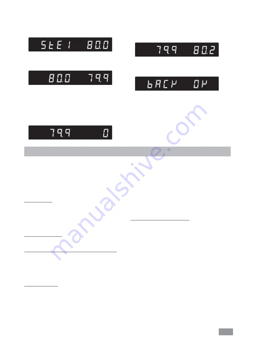
Input the calibration value from the reference mesuring 
instrument (e.g. 80.2 °C) with the “

Pump

 (

+

)“ button 

(

H

) or “

Pump

 (

-

)“ button (

I

).

Confirm the value by pressing the “

OK/Pump

“ button (

G

). 

Back to previous screen for input a new value by press-
ing the “

Temp

“ button (

D

).

Back

OK

The first point calibration is finished now.
Calibration of the other points is performed in the same 
way.

The temperature measured by the unit appears on the 
left hand side.

Set the first point temperature (e.g. 80 °C). Confirm the 
setting by pressing the “

OK/Pump

“ button (

G

). 

Left area of the display appears the set value (80 °C) and 
the right area of the display appears the actual tempera-
ture value measured. The set LED (

M

) flashes briefly. 

The unit now starts and controls to the set value. When 
the temperature has reached the set value and has be-
come constant, the “Set” LED (

M

) no longer flashes and 

the following display appears.

Содержание CF.EG28.N10.80.8

Страница 1: ...20000004066b IKA ICC basic ICC basic_062017 ...

Страница 2: ...signation 1 Operator panel and display 2 Mains switch 3 Power socket 4 Buoyage 5 Heater 6 Stand 7 Pt 100 Pt 1000 temperature sensor 8 Handle 9 Fan 10 RS 232 port 11 USB port 12 Clamp 13 Cable clip 8 2 Fig 2 3 10 7 11 9 12 13 ...

Страница 3: ...and display 9 Commissioning 10 Setting the safety temperature 10 Menu settings 11 Menu structure 11 Basic guide to setting the menu options 11 Operating mode MODE 11 Maximum temperature HI T 11 Minimum temperature LO T 11 Maximum speed HI R 11 Minimum speed LO R 11 Fluid type FLUI 11 The type of temperature PID control arithmetic AUTO 11 Alarm and key tone BEEP 12 Calibration CALI 12 Interface and...

Страница 4: ... EN ISO 12100 Explication of warning symbols Indicates an extremly hazardous situation which if not avoided will result in death serious injury Indicates a hazardous situation which if not avoided can result in death serious injury Indicates a potentially hazardous situation which if not avoided can result in injury Indicates practices which if not avoided can result in equipment damage Indicates ...

Страница 5: ...nhibit fire or explosions or comprehensive monitoring equipment Process pathogenic material only in closed vessels under a suitable fume hood Please contact IKA application support if you have any question If the OFF switch is not within reach when device is operating an EMERGENCY STOP switch that can be easily accessed must be installed in the work area A laboratory circulator heats and circulates...

Страница 6: ... the heater The temperature of the heater can be very high After a power failure during operation the device may start automatically depending on operating mode Transport the device with care Do not transport or empty the bath while it is still hot This may result in accidents especially scalding injuries In order to prevent the power cable from falling into the fluid the mains cable must be se cur...

Страница 7: ...d by third parties Unpacking Delivery scope ICC baisc Mains cables Screwdriver use for safety circuit Operating instructions Warranty card Preparations Setting up Securely fix the immersion circulator on the bath Place the device on an even stable clean nonslip dry and fireproof surface Keep at least 20 cm of open space at the front and rear side When a plastic bath is used please ensure that the he...

Страница 8: ...bi distilled water are unsuitable for operation due to corrosive properties of these media High purity water and distillates are suitable as a medium after adding 0 1 g soda Na2CO3 sodium carbonate per liter of water o Note The temperature limit values are adjustable in accordance with the fluid used Nomenclature for IKA fluids CF EG28 N10 80 8 1 Classification HF Heating Fluid CF Cooling Fluid UF ...

Страница 9: ...avigation selecting the settings in the menu G OK Pump button Start stop the pump function Confirm the menu settings H Pump button Increase the pump speed setting value Change the value setting in the menu I Pump button Decrease the pump speed setting value Change the value setting in the menu J Menu button Press it once menu option is display Press it a second time back to the working screen K LED...

Страница 10: ...mode mode g Safety temperature safe i h After that following two screens appear alternatively Then the device enters standby status and is ready for op eration Change the temperature setting with Temp button E or Temp button F Change the pump speed setting with Pump button H or Pump button I In standby status activate the heating function by pressing the Temp button D The device start heating func...

Страница 11: ...ptions Enter the menu by pressing Menu button J Press the Temp button E or Temp button F to change the menu options Press the Pump button H or Pump but ton I to change the value settings in the menu Confirm the menu settings by pressing the OK Pump button G Operating mode MODE Mode A After power on power failure no automatic restart of functions Mode B After power on power failure automatic re star...

Страница 12: ...time Td s is the derivative time and de termines how strongly the rate of change of the control deviation affects the control variable Td compensates for rapid control deviations A high Td means a smaller and slower effect on the control variable Td values that are too small can lead to instability of the controller AUTO 0 For special requirements AUTO 0 can be used with manual adjustment of the c...

Страница 13: ...ss procedure data transfer from the stirrer machine to the computer takes place only at the computer s request Command syntax and format The following applies to the command set Commands are generally sent from the computer Master to the device Slave The device sends only at the computer s request Even fault indications cannot be sent spontaneously from the device to the computer automation system...

Страница 14: ...et the pump speed XXX OUT_SP_42 n Set the WD safety speed with echo of the set defined value OUT_WD1 n Start the watchdog mode 1 and set the time for the watchdog to n 20 1500 seconds Echo of the Watchdog time During a WD1 event the heating and pump functions are switched off This command needs to be send within the watchdog time OUT_WD2 n Start the watchdog mode 2 and set the watchdog time to n 20...

Страница 15: ...nly after it has been cleaned and is free from any materials which may constitute a health hazard For repair please request the Decontamination Cer tificate from IKA or download printout of it from the IKA website www ika com If you require servicing return the device in its original packaging Storage packaging is not sufficient Please also use suitable transport packaging Error codes Any malfuncti...

Страница 16: ...t the service department Send the device for repair including a short description of the fault Accessories Tubing hoses adapters and couplings LT 5 20 Metal hose isolated M16 x 1 LT 5 21 PTFE hose isolated M16 x 1 H PVC 8 PVC hose nominal width 8 H PVC 12 PVC hose nominal width 12 H SI 8 Silicone hose nominal width 8 H SI 12 Silicone hose nominal width 12 Tubing Insulations ISO 8 Insulation 8 mm I...

Страница 17: ...s III FL suitable for flammable and non flammable fluids Safety circuit adjustable C 0 160 Safety temperature display LED Heating capacity W 2000 230 VAC 1000 115 VAC 760 100 VAC Pump speed adjustable rpm 1000 3200 Max pump pressure suction bar 0 3 0 2 Max flow rate at 0 bar l min 18 Sub level protection Yes Interface USB RS 232 Permitted on time 100 Protection class according to EN 60529 IP 21 Protec...

Страница 18: ...be liable for freight costs The warranty does not cover worn out parts nor does it apply to faults resulting from improper use insufficient care or maintenance not carried out in accordance with the instructions in this operating manual Pump performance curve Fig 9 Pump performance curve measured with water Measurements done according DIN 12876 2 with water at 20 C pump in a closed loop circuit 0 ...

Отзывы: