background image

Maintenance 

Draco tera IP Gateway 

36 

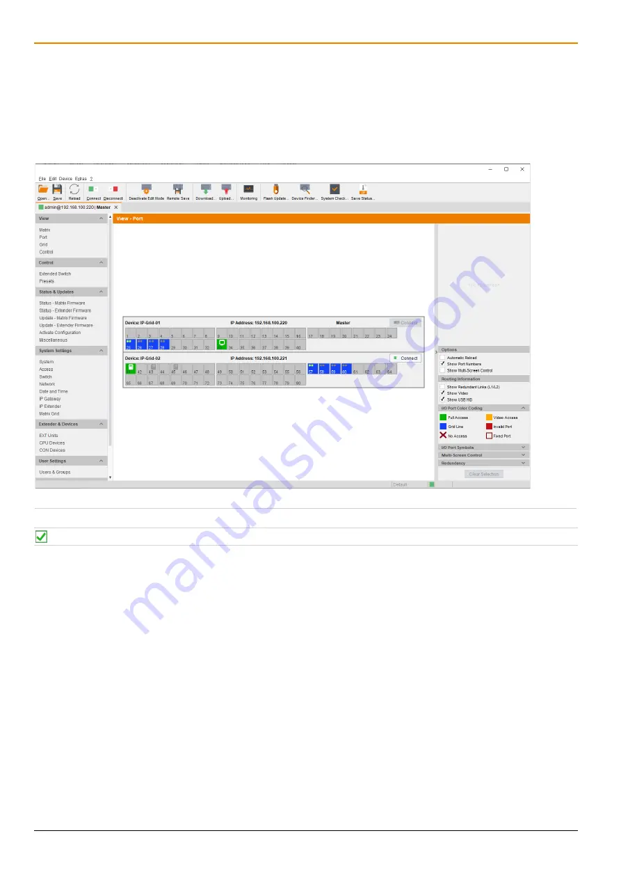
8.2  Querying the Port Status of a Matrix Grid 

In this menu the connections and the switching status between the various CON and CPU Devices are shown within 
the Matrix Grid. 
The port view is divided into the different Grid matrices. As a result, each matrix is displayed in an optimized view of 
24 ports per line to be able to also show a larger number of ports. 

  Click 

View > Port

 in the task area to display the current connections. 


Fig. 18 

Management software menu 

View - Matrix


 Functions, colors, and symbols used in the Grid Port View are explained in the matrix user manual. 


Содержание Draco tera 480 Series

Страница 1: ...Document IP Gateway xx_REV01 00_en Edition 2022 11 22 USER MANUAL Draco tera IP Gateway Functional Quick Setup Guide Series 480...

Страница 2: ...ote the change log for this manual in chapter 15 page 46 The manufacturer reserves the right to change specifications functions or circuitry of the series described here without notice Information in...

Страница 3: ...Gateway CONs connected via IP Gateway 13 4 2 Product Types 14 4 2 1 Draco tera flex Grid Cat X 1G and Fiber 1G 14 4 2 2 IP Gateway Board for Draco tera enterprise 14 4 3 Accessories 14 5 Access Option...

Страница 4: ...8 1 Querying the Device Status via Management Software 35 8 2 Querying the Port Status of a Matrix Grid 36 8 3 Querying the Network Status 37 9 Troubleshooting 38 9 1 IP Connection Failure 38 10 Tech...

Страница 5: ...a hazardous situation which if not avoided could result in minor or moderate injury NOTICE NOTICE identifies information if not observed endangers the functionality of your device or the security of y...

Страница 6: ...ick each means a click with the primary left mouse button If the right mouse button has to be used this is explicitly declared in the description 1 5 Intended Use The IP Gateway is used to establish c...

Страница 7: ...terference at his own expense Changes or modifications not expressly approved by the party responsible for compliance could void the user s authority to operate the equipment Shielded cables must be u...

Страница 8: ...your data Take any required ESD precautions Installation Location While operating the device can get warm Damage to the device can occur in a damp environment Use the device only in dry indoor environ...

Страница 9: ...d charges lectrostatiques Emplacement de l installation Pendant le fonctionnement le p riph rique peut chauffer Le p riph rique peut tre endommag dans un environnement humide N utilisez le p riph riqu...

Страница 10: ...for using as IP Gateway with eight IP KVM channels per rack unit 4 1 1 Installation Example Matrix System with IP Gateway Board Fig 1 Example 1 Matrix system installation with IP Gateway board 1 Sourc...

Страница 11: ...eway Board Fig 2 Example Matrix Grid Installation with two Matrices connected via IP Gateway Board 1 Draco tera flex with 10G IP Gateway board configured for eight 1G KVM channels 2 10G straight fiber...

Страница 12: ...IP Gateway Fig 3 Example Matrix system with IP Gateway CONs connected via IP Gateway 1 Draco tera flex with 10G IP Gateway board configured for eight 1G KVM channels 2 10G straight fiber cable with e...

Страница 13: ...IP Gateway Description 13 4 1 4 Installation Example Matrix Grid with two Matrices and IP Gateway CONs connected via IP Gateway Fig 4 Matrix Grid with two matrices and IP Gateway CONs connected via I...

Страница 14: ...contact the sales team for availability estimated October 2022 Product type Description 480 IPG Draco tera enterprise IP Gateway board for transmission of up to 8 KVM connections 1G configurable for...

Страница 15: ...update Local backup option Documentation 5 1 Command Mode To start the command mode use a keyboard sequence Hot Key at the keyboard of a CON Unit plugged in a KVM device The command mode can also be...

Страница 16: ...ht Alt Change the current Hot Key via Hot Key Code exemplary To change the current Hot Key to e g 2x Left Alt enter Hot Key c 5 Enter Set a freely selectable Hot Key exemplary To set a freely selectab...

Страница 17: ...tructure 1 Menu bar 2 Toolbar 3 Tab bar shows connections or configurations 4 Task area 5 Task menu 6 Task menu item 7 Status bar shows config version activated Edit Mode and online mode 8 Working are...

Страница 18: ...oad a locally saved configuration 2 Save a configuration locally 3 Reload the current configuration 4 Connect to the matrix 5 Disconnect from the matrix 6 Activate deactivate the edit mode 7 Save the...

Страница 19: ...in the menu bar can be executed with the provided keyboard commands e g press Ctrl s to execute Save that are listed to the right of the respective menu item 5 2 5 Management Software Reload Options...

Страница 20: ...rt Click with the left mouse button once or twice on the head of the sorted column The displayed arrow disappears 5 2 8 Management Software Filter Function Lists and tables in the management software...

Страница 21: ...guration in a PDF file The report function can be used in both online and offline mode of the management software To create a report proceed as follows 1 Select File Report in the menu bar A selection...

Страница 22: ...ns Draco tera IP Gateway 22 4 Go to the preferred location for storage of the report 5 Click Finish to confirm the report The report will be created as a PDF file Fig 8 Management software File Report...

Страница 23: ...onnected matrix controller board s I O boards CON Units CPU Units sources and sinks etc The initial configuration has been set system settings e g network settings The logical devices have been create...

Страница 24: ...ry RAM Recommended 1 GB Operating system Microsoft Windows 8 Windows 8 1 Windows 10 Windows 11 Management software with integrated Java Runtime Tera Tool Downloaded from https www ihse com software Ne...

Страница 25: ...plication in the Firewall If using the management software the Java application file javaw exe has to be released in the firewall settings to use the management software Contact your administrator to...

Страница 26: ...nagement software by a double click on the program icon on the desktop or the file in the directory The management software starts in offline mode Fig 9 Management software Landing page in offline mod...

Страница 27: ...software 2 Click Connect in the tool bar A login dialog appears 3 Enter the IP address according to the network configuration of the matrix By default the IP address of the matrix is 192 168 100 99 an...

Страница 28: ...of a specific matrix is unknown and should be accessed via IP Fig 11 Management software menu Device Finder The following device information is shown in the Device Finder Information Description Broad...

Страница 29: ...cast address By default the search is set via broadcast 255 255 255 255 3 Click Connect in the last column of the Device Finder to establish direct connection to the respective device within the same...

Страница 30: ...establish connections to another IP Gateway boards or to an IP Gateway extender To set an IP Gateway connection between two matrices it is necessary to configure both matrices Fig 12 Management softw...

Страница 31: ...onding selection box of the port to be configured within the Type column and select Grid Fig 13 Management software menu System Settings IP Gateway Select Channel Type 6 Double click in the respective...

Страница 32: ...u Fig 15 Management software menu System Settings IP Gateway Selected Grid Channel 9 Click Apply to confirm the selection The data of the selected Master Matrix channel is read and send to the selecte...

Страница 33: ...tination data 8 Double click in the respective Destination IP Address field and enter the destination IP address of the IP Gateway board of the Sub Matrix 9 Press Enter to confirm the destination IP a...

Страница 34: ...ot with the IP Gateway board under Slot of which an IP Gateway connection has to be deleted 5 Click the red cross in the respective line to delete the connection of an IP Gateway board The connection...

Страница 35: ...s to the matrix are displayed in this menu Click View Matrix in the task area to display the current connections Slots with IP Gateway boards are designated in the matrix view 1 Fig 17 Management soft...

Страница 36: ...ix Grid The port view is divided into the different Grid matrices As a result each matrix is displayed in an optimized view of 24 ports per line to be able to also show a larger number of ports Click...

Страница 37: ...controller board with the left mouse button The corresponding network status will be displayed in the panel on the right side of the working area The available information can be faded in or hidden by...

Страница 38: ...Matrix Grid connection available The destination type is set to EXT Unit Set the designation type to Grid The destination data is wrong Check the designation IP address of both IP Gateway boards Check...

Страница 39: ...mponent such as an ethernet hub switch or router is not allowed Operation with several patch fields is possible Establish a point to point connection Avoid routing Cat X cables along power cables NOTI...

Страница 40: ...xtension distance is halved Maximum Transmission Range for Video and USB HID Signals End to End Connection Type of cable Maximum transmission range Cat X installation cable AWG24 140 m 460 ft Cat X pa...

Страница 41: ...um transmission range Single Mode 9 m 1G 10 000 m 32 808 ft Single Mode 9 m 3G 5 000 m 16 404 ft Multi Mode 50 m OM3 1G 3G 1 000 m 3 280 ft Multi Mode 50 m 1G 3G 400 m 1 312 ft When using single mode...

Страница 42: ...necessary Issue date of the existing manual Nature circumstances and duration of the problem Components included in the system such as graphic source CPU OS graphics card monitor USB HID USB 2 0 devic...

Страница 43: ...systems via matrix CPU Unit Encoder extender module to connect to a source Fiber Single mode or multi mode fiber cables KVM Keyboard video and mouse MTBF Mean Time Between Failure MTBF is measured in...

Страница 44: ...onnect 39 M Maintenance 35 O Operation Querying the Device Status 35 Querying the Network Status 37 Querying the Port Status 36 P Pinout 41 Fiber SFP Type LC Interconnect 41 RJ45 Interconnect 41 Produ...

Страница 45: ...ement software File Report Save Report 22 Fig 9 Management software Landing page in offline mode 26 Fig 10 Management software dialog Connect 27 Fig 11 Management software menu Device Finder 28 Fig 12...

Страница 46: ...s an overview about the most important changes available such as new functions changed configuration or operation Edition Date Firmware version Software version Chapter New functions changes REV01 00...

Отзывы: