background image

13

UK

9.2  Operating mode

The length of the preceding undamping determines whether the yellow LED 

comes on with a delay (→ 9.2.1) or without delay (→ 9.2.2) when a target moves 

into the enable zone� In any case, the outputs switch on without delay�
In case of undamping the outputs switch off and the yellow LED goes out without 

delay� 
In case of damping in the close range the outputs switch off immediately whereas 

the yellow LED goes out with a delay of approx� 2 s� When the LED goes out the 

outputs are maintained in the safe state ("0")� Thus, switching on again in the en-

able zone is not possible� Enabling is done by undamping (> 30 mm) of more than 

2 s or by interrupting the voltage (→ 5.2 Protection against simple defeating)�

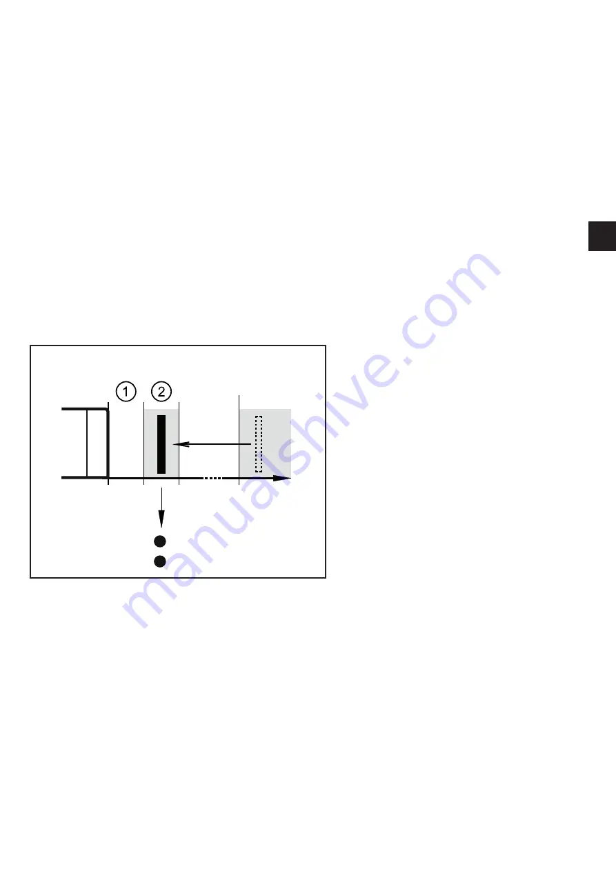
9.2.1  Delayed switching of the LED

Undamping > 2 s:

30

0

> 3 s

mm

Signal
Power

If the target was away from the 

sensor for more than approx� 2 s 

(> 30 mm), the yellow LED goes on 

with a delay of approx� 3 s in case of 

damping in the enable zone�
This is also the case if the target is in 

the enable zone when the voltage is 

switched on�

1:  close zone

2:  enable zone

Содержание GM701S

Страница 1: ...Original operating instructions Fail safe inductive sensor GM701S UK 80236831 00 09 2016 ...

Страница 2: ...he sensing face 8 6 2 Installation conditions 8 7 Electrical connection 10 8 Set up 10 8 1 Setting aid 10 8 2 Determine the enable zone 10 8 3 Deactivate setting aid 11 9 Operation 12 9 1 Switching state of the outputs 12 9 1 1 The safe state 12 9 1 2 The switched state 12 9 1 3 Output characteristics 12 9 1 4 Cross faults 12 9 2 Operating mode 13 9 2 1 Delayed switching of the LED 13 9 2 2 Switch...

Страница 3: ...to familiarise yourself with operating conditions installation and operation Follow the safety instructions 1 1 Symbols used Instructions Cross reference Important note Non compliance can result in malfunction or interference Information Supplementary note LED on LED off LED flashes 2 Hz LED flashes quickly 5 Hz 1 2 Warning signs used WARNING Warning of serious personal injury Death or serious irr...

Страница 4: ...y a qualified electrician trained in safety technology The applicable technical standards for the corresponding application must be complied with For installation the requirements according to EN 60204 must be observed In case of malfunction of the unit please contact the manufacturer Tampering with the unit is not allowed Disconnect the unit externally before handling it Also disconnect any indep...

Страница 5: ...nected to the system In case of faults within the fail safe sensor which result in the defined safe state take measures to maintain the safe state when the complete control system continues to be operated Replace damaged units 3 Items supplied 1 fail safe sensor GM701S with premounted angle bracket 1 Allen key for fixing the fail safe sensor onto the angle bracket 1 original operating instructions...

Страница 6: ... 5 2 for non flush installation 6 Installation The fail safe inductive sensor has been certified by TÜVNord The unit is suited for applications up to 5 Hz 5 Function 0 1 1 dual LED signal yellow power green 2 close zone 3 enable zone 4 safe switch off distance sar 5 target 5 1 Enable zone The outputs OSSD are only enabled when a damping target is present in the en able zone Outside this enable zon...

Страница 7: ...n the enable zone unintention ally In addition the sensor has the following switching characteristics to make simple defeating of its safety function more difficult 1 By slowly introducing a metallic object into the enable zone the outputs are immediately switched but displayed by the LED with a delay of approx 3 s 9 2 1 Delayed switching of the LED By doing so the object is generally in the close...

Страница 8: ...socket according to the manufacturer s indications Observe the tightening torque for the ifm socket e g EVxxxx 0 6 1 5 Nm 6 2 Installation conditions The unit is non flush mountable in steel in accordance with IEC 60947 5 2 type I2C40SP2 In addition one side of the unit can be mounted flush with steel ...

Страница 9: ...60947 5 2 type I1C40SP2 Ensure the unit cannot work loose Tighten captive screws with 1 Nm Limit the use of oblong holes to the initial setting Adhere to the installation conditions in accordance with the figures 1 to 5 1 80 80 105 3 2 Angle mounting Channel mounting 80 80 4 5 80 80 80 ...

Страница 10: ...equires the safe separa tion between power supply and transformer 8 Set up 8 1 Setting aid For easy and reliable installation the sensor features an optical setting aid to visualise the enable zone 30 0 5 s mm Signal Power The setting aid is activated by placing a metal object in front of the fail safe sensor close range After approx 5 s the yellow LED starts to flash the setting aid is active Whi...

Страница 11: ... outside the enable zone in either direction the LED starts to flash again 1 close zone 2 enable zone 8 3 Deactivate setting aid 30 0 2 s mm Signal Power 2 s Signal Power If the sensor is undamped for more than 2 s 30 mm the setting aid is switched off and the yellow LED goes out This can also be achieved by power off 1 close zone 2 enable zone ...

Страница 12: ...61131 2 type 1 or 2 Logic 1 15 V 2 15 mA 11 V 15 30 mA Logic 0 5 V leakage current 0 2 mA pull down current typ 30 mA The interface corresponds to interface type C class 0 according to the ZVEI position paper Klassifizierung binärer 24 V Schnittstellen mit Testung im Bereich der Funktionalen Sicherheit Classification of binary 24V interfaces tested with regard to functional safety 9 1 4 Cross faul...

Страница 13: ... with a delay of approx 2 s When the LED goes out the outputs are maintained in the safe state 0 Thus switching on again in the en able zone is not possible Enabling is done by undamping 30 mm of more than 2 s or by interrupting the voltage 5 2 Protection against simple defeating 9 2 1 Delayed switching of the LED Undamping 2 s 30 0 3 s mm Signal Power If the target was away from the sensor for mo...

Страница 14: ...ng the close range non safety related zone 100 ms Response time when approaching the enable zone enable time typ 100 ms 200 ms Risk time response time for safety related faults 100 ms Permissible dwell time in the close range approx 2 s Delay time to activate the setting aid 8 1 approx 5 s Dwell time in the undamped condition 30 mm to return into the operating mode 8 3 Deactivate setting aid appro...

Страница 15: ...15 UK 1 0 t 1 0 t 1 Test pulse duration 2 Test pulse interval Tp pulse package 3 Test pulse interval T Test pulse interval T repetition pulse package min 30 ms max 50 ms ...

Страница 16: ...h outputs switched off 0 0 Signal Power Taget outside the enable zone operating mode or in the enable zone setting aid Both outputs switched off 0 0 Signal Power Target in the enable zone operating mode Both outputs enabled 1 1 Signal Power Target outside the enable zone setting aid Both outputs switched off 0 0 Signal Power Internal or external fault 11 Troubleshooting 0 0 1 0 1 0 ...

Страница 17: ...1 SILcl 3 Application Type of operation continuous operation maintenance free Electrical data Electrical design DC PNP Operating voltage 24 DC 19 2 30 DC Rated insulation voltage 30 Current consumption 15 Protection class III Reverse polarity protection yes Outputs Output function 2 x OSSD A1 and A2 Output data Interface type C class 0 Output voltage at 24 V compatible with EN 61131 2 inputs type ...

Страница 18: ...ssible Salt spray no Protection IP 65 IP 67 Tests approvals EMC IEC 60947 5 2 IEC 60947 5 3 EN 60947 5 2 EN 61000 4 2 ESD 6 kV CD 8 kV AD EN 61000 4 3 HF radiated 20 V m EN 61000 4 4 Burst 2 kV EN 61000 4 6 HF conducted 10 V EN 61000 4 8 30 A m EN 55011 class B Shock resistance IEC 60947 5 2 Vibration resistance IEC 60947 5 2 Safety classification Mission time TM 175200 20 years Safety related rel...

Страница 19: ...es and sensor does not switch Undervoltage Overvoltage Correct the voltage 10 Technical data Sensor does not switch not even after undamping and redamping Sensor was brought into the safe state logic 0 Cause cross fault between both outputs A1 and A2 cross fault between one output A1 or A2 and the supply voltage error in the sensor detected Switch the operating volt age off and on again Check wiri...

Страница 20: ...H PFHD Probability of dangerous Failure per Hour PL Performance Level PL to EN ISO 13849 1 SIL Safety Integrity Level SIL 1 4 to IEC 61508 The higher the SIL the lower the probability that a safety function will fail SILcl Safety Integrity Levelclaim limit According to IEC 62061 TM Mission time Lifetime to EN 60947 5 3 max service life ...

Страница 21: ...21 UK ...

Отзывы: