Wire Connection to Controller
p.13
2
Connecting a door lock
●
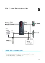
Connect (+) wire of door lock to +12V wire of power supply.
●
Connect (-) wire of door lock to white wire of reader module.
3
Connecting an exit button
●
Connect Green wire of exit button input to one wire between wires of exit button.
●
Connect GND wire of power supply to the other wire.
4
Connecting a door sensor
●
Connect COM terminal of door sensor to Blue wire of door sensor input.
●
Connect NO terminal of door sensor to GND of power supply.
5
Connecting a door lock type
●
In a power fail safe, connect GND wire of power supply to Yellow wire of door lock type
input.
●
In a power fail secure, put a floating state on Yellow wire of door lock type input.
6
RS485 Communication port connection
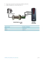
The INC300 for RS485/RS232 converter is required to connect a product to the PC.
●
Connect gray wire for RS485(A) to 485(+) terminal of converter.
●
Connect orange wire for RS485(B) to 485(-) terminal of converter.
Содержание Star IP-RFL200C
Страница 1: ......
Страница 9: ...Identifying Supplied Parts 4 p 6 Please unpack and check the contents of the box ...
Страница 13: ...p 10 ...
Страница 14: ...Color Coded Wiring Table 7 p 11 ...
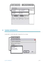
Страница 21: ...p 18 System Initialization 4 System Initialization StarRFL200C iPASS IP RFL200C is initialized by the software ...

