


51
Response FF80
- Installation
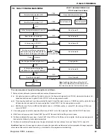
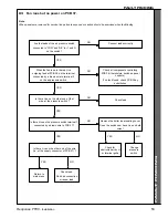
81 CH but no HW
This indicates an 'open circuit' or
'short circuit' HW sensor or lead.
Unplug the lead from the sensor
and connect it temporarily to a
replacement sensor, if available.
(Alternatively, see footnote)
Does the flashing stop ?
Is the HW light on PCB 38
flashing
?
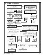
Is there a flow of at least 3.5 litres per
minute (or about 1 pint in 10 seconds) when
a hot tap is turned on ?
Change the flow switch
NO
YES
NO
YES
NO
YES
NO
NO
Adjust the flow rate
restrictor to give the
required flow.
If this is not possible rectify
a system pipework defect
or a supply pressure
problem.
Switch off the boiler.
Unplug the flow switch lead at
the inline connector.
Measure continuity between
the switch leads and turn a
hot tap on.
Does the switch close ?
Reconnect the flow
switch.
Unplug the lead from the
HW sensor and transfer
temporarily to a
replacement sensor.
Will the boiler operate ?
Replace the HW sensor (which
has failed 'low resistance')
Check all connections to
PCB 38.
Check for moisture on
PCB 38.
If no fault found check
PCB 38 by substitution.
Note.
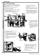
When panels are removed for service, live parts are exposed so caution should be exercised when fault-finding.
YES
NO
Check - and
repair or
replace the
sensor
lead.
Does the
flashing stop
now ?
Check all connections
to PCB 38.
Check for moisture on
PCB 38.
If no fault found check
PCB 38 by substitution.
Replace the
HW sensor
YES
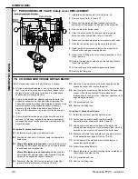
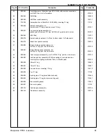
Checking CH and HW thermistor sensors
The sensors can be checked by measuring their resistance,
using a suitable multimeter connected across the sensors'
terminal pins.
At room temperature
expect
9,000 to 11,000
Ohms
At 60°C.
expect
2,000 to 2,500
Ohms
At 85°C.
expect
1,000 to 1,500
Ohms
FAULT FINDING
F
AUL
T FINDING
Содержание Response FF80
Страница 1: ......
Страница 6: ...6 Response FF80 Installation GENERAL 1 BOILER WATER CIRCUIT DIAGRAMS...
Страница 63: ...63 Response FF80 Installation...
Страница 64: ...64 Response FF80 Installation...