


43
Response FF80
- Installation
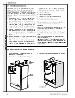
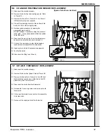
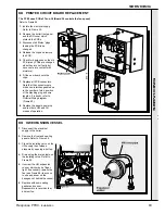
68 PRINTED CIRCUIT BOARD REPLACEMENT
SER
VICING
SERVICING
The FF 80 uses PCBs 37 and 38 (Board 38 controls the fan speed)
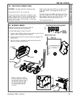
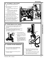
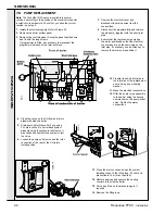
69 HW EXPANSION VESSEL
1.
Disconnect the electrical
supply to the boiler.
2.
Remove the front and sealing
panels. Refer to Frame 48.
3.
Close the isolating valve on the
HW supply then release
pressure by opening a hot tap.
4.
Drain using the drain nipple on
the isolating valve. Refer to
Frame 52.
5.
Unscrew the HW expansion
vessel, which may be finger-
tight. If necessary, remove the
fan (see Frame 66) to access
to use a spanner on the
hexagon nut behind the vessel.
6.
Replace with new sealing
gasket and vessel.
Reassemble in reverse order
and test fire.
Refer to Frame 48.
1.
Isolate the electrical supply.
Refer to Frame 55.
2.
Remove the boiler front panel
and the RH cover which
protects the PCBs.
3.
Disconnect all 'Molex' plugs
feeding the PCB to be
changed.
4.
Release the clips and remove
the PCB.
5.
Check for dampness on the old
PCB (many PCBs are changed
when they are not faulty but
have come into contact with
moisture).
6.
Fit the new board onto the
clips.
7.
Replace all PCB connectors.
Note that the connectors are
made non-interchangeable due
to the number of pins, position
of the blanking plug and wire
lengths. If in doubt, refer to
Pictorial Wiring diagram
(Frame 40).
8.
Replace the panels, power up
and test both HW and CH
modes of operation.
Содержание Response FF80
Страница 1: ......
Страница 6: ...6 Response FF80 Installation GENERAL 1 BOILER WATER CIRCUIT DIAGRAMS...
Страница 63: ...63 Response FF80 Installation...
Страница 64: ...64 Response FF80 Installation...