IDEAL Response FF80 Скачать руководство пользователя страница 40

40

Response FF80  

- Installation

SERVICING

SER

VICING

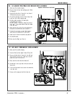
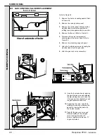
63 GAS CONTROL VALVE REPLACEMENT

Refer to Frame 55.

1.

Remove the front and sealing panels. Refer
to Frame 48.

2.

Remove the casing bottom panel.

3.

Remove the control panel. Disconnect the
electrical leads (noting their position for
refitting) and place panel safely to one side.

4.

Remove the fan unit. Refer to Frame 49.
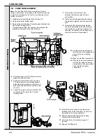
5.

Disconnect the burner skin pressure
sensing pipe at the burner base. Refer to
Frame 50.

6.

Remove the pressure gauge sub panel.
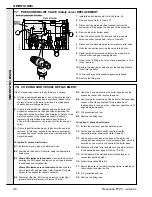
7.

Undo the 2 retaining screws and unplug the
electrical leads from the gas valve.

8.

Undo the gas cock union connection.

9.

Undo the 2 extended nuts retaining
the gas injection pipe and withdraw
the pipe, taking care not to lose the
'O' ring seal. Undo the third nut and
the gas outlet manifold block.

10.

Supporting the valve, undo the 4
retaining screws and withdraw the
gas valve, leaving the plate with
the 3 studs in place.

11.

Transfer the gas cock union and
elbow assembly to the new gas
valve, reusing the 4 M5 x 10
screws, together with the new 'O'
ring seal provided.

Содержание Response FF80

Страница 1: ......

Страница 2: ...half that of other combis makes the Response ideal for any kitchen It can be installed inside a standard size kitchen wall unit without insulation and with minimal ventilation or it can be mounted to...

Страница 3: ...39 Table 3 Performance Data DOMESTIC HOT WATER Response FF80 Maximum Burner pressure HOT mbar in w g 14 8 5 9 Input based on nett CV kW Btu h 26 4 90 000 Input based on gross CV kW Btu h 29 3 100 000...

Страница 4: ...se FF80 Installation NOTE TO THE INSTALLER LEAVE THESE INSTRUCTIONS ADJACENT TO THE GAS METER Response FF80 Natural gas only G C Appliance No 47 415 09 B G Certified P I No 87AR183 Destination Countri...

Страница 5: ...stic hot water calorifier A circulating pump pressure gauge safety valve and expansion vessels for both central heating CH and domestic hot water DHW are provided The CH flow temperature is controlled...

Страница 6: ...6 Response FF80 Installation GENERAL 1 BOILER WATER CIRCUIT DIAGRAMS...

Страница 7: ...om inside the building where wall thicknesses do not exceed 600mm 24 Where the space into which the boiler is going to be installed is less than the length of flue required the flue must be fitted fro...

Страница 8: ...imber Framed Buildings If the boiler is to be fitted in a timber framed building it should be fitted in accordance with the British Gas publication Guide for Gas Installations in Timber Frame Housing...

Страница 9: ...n for smallbore and microbore systems BS 5449 The domestic hot water system should be in accordance with BS 5546 and BS 6700 Copper tubing to BS 2871 1 is recommended for water carrying pipework and M...

Страница 10: ...boiler except for bathroom installations where the point of connection to the mains MUST be situated outside of the bathroom Note Where a room sealed appliance is installed in a room containing a bat...

Страница 11: ...the boiler and drain the system while still hot Refill and vent the system Re pressurise the system to the desired charge pressure see Table 6 6 Size of expansion vessel For the system water expansio...

Страница 12: ...ss than 3m 10 and must not include any other valves b The balancing valve MUST be at least one turn open 8 Hydraulic resistance Having subtracted the hydraulic resistance of the boiler the head availa...

Страница 13: ...DHW Flow switch 25 Automatic air vent 26 Heat exchanger 27 Burner sensing pipe 28 Fan sensing pipe 29 Sensing pipe clamp 9 Boiler overheat stat 10 Water pressure switch 15 Pressure gauge 17 Fan assem...

Страница 14: ...in one Pack A together with a standard flue assembly for lengths up to 600mm rear or side flue outlet in Pack B Unpack and check the contents Hardware Pack z M6 x 10 Pp Hd screw 4 off z 1 2 x 15mm cop...

Страница 15: ...duct s in order to prevent interference between flue duct connectors and the boiler flue elbow For side flue option PROCEED TO FRAME 20 10 DETERMINING THE FLUE LENGTH AND FLUE PACKS REQUIRED Use a max...

Страница 16: ...ION 11 REAR FLUE ASSEMBLY Exploded View REAR FLUE OUTLET 12 WALL MOUNTING TEMPLATE Rear Flue IMPORTANT For direct mounting wall mounting frame on wall choose one black dot in each group If using the s...

Страница 17: ...and off channels To allow pipework to be taken upwards z z z z z Insert wall plugs z z z z z Put the screws into the wall plugs and leave 10mm proud z z z z z Fasten each channel to the frame with the...

Страница 18: ...ing the cardboard support aid 5 Remove the cardboard support and any burrs For flue lengths greater than 600mm 23 5 8 refer to Frames 30 to 32 Flue Extension Ducts 16 FITTING THE FLUE 1 Attach the cla...

Страница 19: ...For standard installations use the short wood screw If the stand off option is used secure the support bracket using the spacer bracket and long wood screw 17 MOUNTING THE BOILER IMPORTANT This must n...

Страница 20: ...has not broken through neatly or c When the wall face is rough and the rubber seal on its own would be ineffective 1 Position the terminal wall plate over the terminal 2 Drill 4 fixing holes with a 7m...

Страница 21: ...holes are drilled 2 When cutting the ducts always use the cardboard support cutting aid provided 1 An optional flue duct extension kit is required for wall thicknesses greater than 504mm 19 7 8 LHS fl...

Страница 22: ...o position the pipes behind the wall mounting plate BEFORE the plate is screwed to the wall Note If the terminal is to be sited within 25 40mm of a corner or vertical pipe refer to Table 3 then the ho...

Страница 23: ...z Insert the wall plugs z z z z z Put the screws into the wall plugs and leave 10mm proud z z z z z Fasten each channel to the frame with the 6mm screws provided z z z z z Hang channels and frame onto...

Страница 24: ...ssure relief valve using the nut and olive supplied in the hardware pack 28 CONNECTING THE TURRET TO THE BOILER SIDE FLUE OUTLET INSTALLATION open ends of the turret clamp under the 2 studs and fixing...

Страница 25: ...c When the wall face is rough and the rubber seal on its own would be ineffective INSTALLATION SIDE FLUE OUTLET 1 Position the terminal wall plate over the terminal 2 Drill 4 fixing holes with a 7mm 1...

Страница 26: ...spaced holes through the flue connector and the outer flue duct Do not drill the inner flue duct 4 Insert the self tapping screws provided to fix the connector in position 5 Fit the inner flue extensi...

Страница 27: ...s 2 Mate the flue to the turret Refer to Frame 28 for details Note To facilitate turret fixing or removal do NOT make good the wall 32 CUTTING THE FLUE TO LENGTH INSTALLATION INSTALLATION 34 SERVICE C...

Страница 28: ...ete assembly back onto the mounting frame Extend a gas supply pipe of not less than 22mm O D copper or 3 4 BSP iron to the boiler A working gas pressure of 20mbar 8 w g must be available at the boiler...

Страница 29: ...r MUST be in accordance with the current I E E BS7671 Wiring Regulations and any local regulations The supply connection is intended to be made via a double pole switch having a 3mm 1 8 contact separa...

Страница 30: ...NG LEGEND b blue bk black br brown r red o orange w white y yellow m mauve pk pink gy grey g y green yellow LEGEND b blue bk black br brown r red o orange w white y yellow m mauve pk pink gy grey g y...

Страница 31: ...t damage However if parts of the pipework run outside the house or if the boiler will be left off for more than a day or so then a frost thermostat should be wired into the system This is usually done...

Страница 32: ...hould check that the inlet presssure test point H is at least 18 mbar when the boiler is firing 13 Set the boiler on off switch C to 0 14 Remove the pressure gauge and tube Replace the sealing screw i...

Страница 33: ...he boiler and check that the boiler is firing at maximum rate c Use a screwdriver to turn the DHW flow adjuster clockwise to reduce the DHW flow rate until a DHW temperature of approximately 35 o C ri...

Страница 34: ...ampling point provided Frame 48 Note If your meter reads CO in parts per million the figure must be divided by 10 000 to convert it to a percentage If the ratio of CO CO2 is less than 004 and the gas...

Страница 35: ...to the fan b Undo the 2 screws securing the pipe clamping plate to the manifold block c Withdraw the clamping plate d Withdraw the pipe from the boiler 3 Rotate the fan body to the right to disengage...

Страница 36: ...ing it in the bayonet fixing and locating it in the retaining bracket 5 Reconnect the pressure sensing pipe to the fan and secure both pipes to the manifold block with the clamping plate 6 Reconnect t...

Страница 37: ...est fire the boiler 1 Disconnect the electrical supply 2 Remove the boiler front and sealing panels Refer to Frame 48 3 Remove the fan refer to Frame 49 the CH and HW thermistors are now exposed 4 Clo...

Страница 38: ...sealing panels Refer to Frame 48 2 Disconnect the leads from the spark electrodes 3 Disconnect the electrical leads from the spark generator 4 Slide out the spark generator in the direction of the arr...

Страница 39: ...age the electrodes 7 Remove the spark and detection electrodes Refer to Frame 59 8 Remove the 3 securing screws and withdraw the burner from the mounting flange 9 Fit the new burner replacing any dama...

Страница 40: ...er base Refer to Frame 50 6 Remove the pressure gauge sub panel 7 Undo the 2 retaining screws and unplug the electrical leads from the gas valve 8 Undo the gas cock union connection 9 Undo the 2 exten...

Страница 41: ...oiler then release CH system pressure by opening one of the CH drain cocks on the isolating valves It is not advisable to release system pressure using the safety valve 12 Offer the gas valve to the p...

Страница 42: ...care when handling the fan in order to preserve the balance of the impeller 6 Fit the new fan ensuring that a All seals are correctly refitted b The sensing pipe clamping plate is correctly refitted c...

Страница 43: ...ehind the vessel 6 Replace with new sealing gasket and vessel Reassemble in reverse order and test fire Refer to Frame 48 1 Isolate the electrical supply Refer to Frame 55 2 Remove the boiler front pa...

Страница 44: ...on and the inlet connection at the rear of the CH return isolating valve 13 Close the drain cocks and open the system isolating cocks fit the filling loop fill vent and pressurise to 1bar or as requir...

Страница 45: ...rain points open all isolating valves and ensure that the boiler is filled vented of air and pressurised before attempting to fire it 22 After a satisfactory test firing remove the filling loop this i...

Страница 46: ...the programmer and withdraw it from the retaining bracket 7 Fit the new programmer and re assemble in reverse order 8 Check the operation of the new programmer 73 WATER PRESSURE SWITCH 1 Disconnect th...

Страница 47: ...w switch ensuring that the locating pin and hole are correctly positioned 9 Complete the reassembly in reverse 76 MAINS TRANSFORMER REPLACEMENT 1 Isolate the electrical supply to the boiler Refer to F...

Страница 48: ...droom the boiler will need to be removed In this case access to the water connection of the expansion vessel will be possible by removing the RH boiler side panel For option B proceed as follows B1 Is...

Страница 49: ...rmostat call for heat CH and Fan lights come on PCB 38 senses this starts the fan at full speed and sends power to the pump and Ignition Control PCB 37 via the casing pressure switch or c Both the abo...

Страница 50: ...res and connections OK YES Is the CH light on PCB 38 flashing Check lead to pump Replace cap Switch off and change pump YES Is the HW light lit on PCB 38 If the boiler has been unused with mains off t...

Страница 51: ...witch close Reconnect the flow switch Unplug the lead from the HW sensor and transfer temporarily to a replacement sensor Will the boiler operate Replace the HW sensor which has failed low resistance...

Страница 52: ...fuse Examine fan harness checking especially for short circuits between wires or terminals If no fault found power up board without fan harness connected Does fuse F1 blow YES NO YES EXIT YES YES Doe...

Страница 53: ...ere Live on the pressure switch terminal 1 connected by a brown wire to PCB 37 YES Is there Live on the other end of the wire i e at the supply connector of PCB 37 YES NO Check lead Find bad connectio...

Страница 54: ...unobstructed by solid matter or moisture Is there Live on the brown lead of the gas valve connector on PCB 37 during an ignition trial period Are both connectors correctly fitted to the gas valve wit...

Страница 55: ...ternally to the burner YES YES NO Rectify poor connections or replace the spark generator or electrodes Remove the fan and burner assembly and reconnect spark leads to the electrode terminals Check th...

Страница 56: ...Rectify any fault Does the boiler now run YES Is this a new installation Has any electrical work been done to the boiler or the house wiring YES Check the polarity of the incoming mains to the boiler...

Страница 57: ...NO FAULT FINDING Check discharge pipe from the safety valve this may well be outside the building Has it been discharging water NO NO YES Is the safety valve free from foreign matter correctly set and...

Страница 58: ...jector 2A Gas valve 3 Detection electrode 4 Spark electrode 17 Fan 27 Burner sensing pipe 28 Fan pressure sensing pipe 53 Fan Burner mounting O ring 54 Fan O ring 55 Sensing pipe O ring manifold block...

Страница 59: ...59 Response FF80 Installation SHORT LIST OF PARTS 89 CONTROLS AREA General Arrangement Response FF 80 5 Air pressure switch 6 PCB 37 7 PCB 38 66 Mains transformer...

Страница 60: ...ectrode Morgan Matroc c w 1 off ignition electrode gasket 1 off M4 x 10 lg pozi pan hd screw 1 off M4 shakeproof washer 1 075173 5 378 931 Air pressure switch SIT ref 0 380 064 1 112417 6 E00 046 PCB...

Страница 61: ...92 41 E00 080 Boiler LH side panel assembly c w 6 off M4 x 10 lg pozi hex hd screws 1 075192 42 E00 081 Boiler RH side panel assembly c w 6 off M4 x 10 lg pozi hex hd screws 1 075193 43 E00 082 Tank c...

Страница 62: ...1997 138 390 A03 Technical Training The Caradon Ideal Technical Training Centre offers a series of first class training courses for domestic commercial and industrial heating installers engineers and...

Страница 63: ...63 Response FF80 Installation...

Страница 64: ...64 Response FF80 Installation...

Отзывы: