3.11
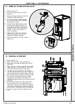
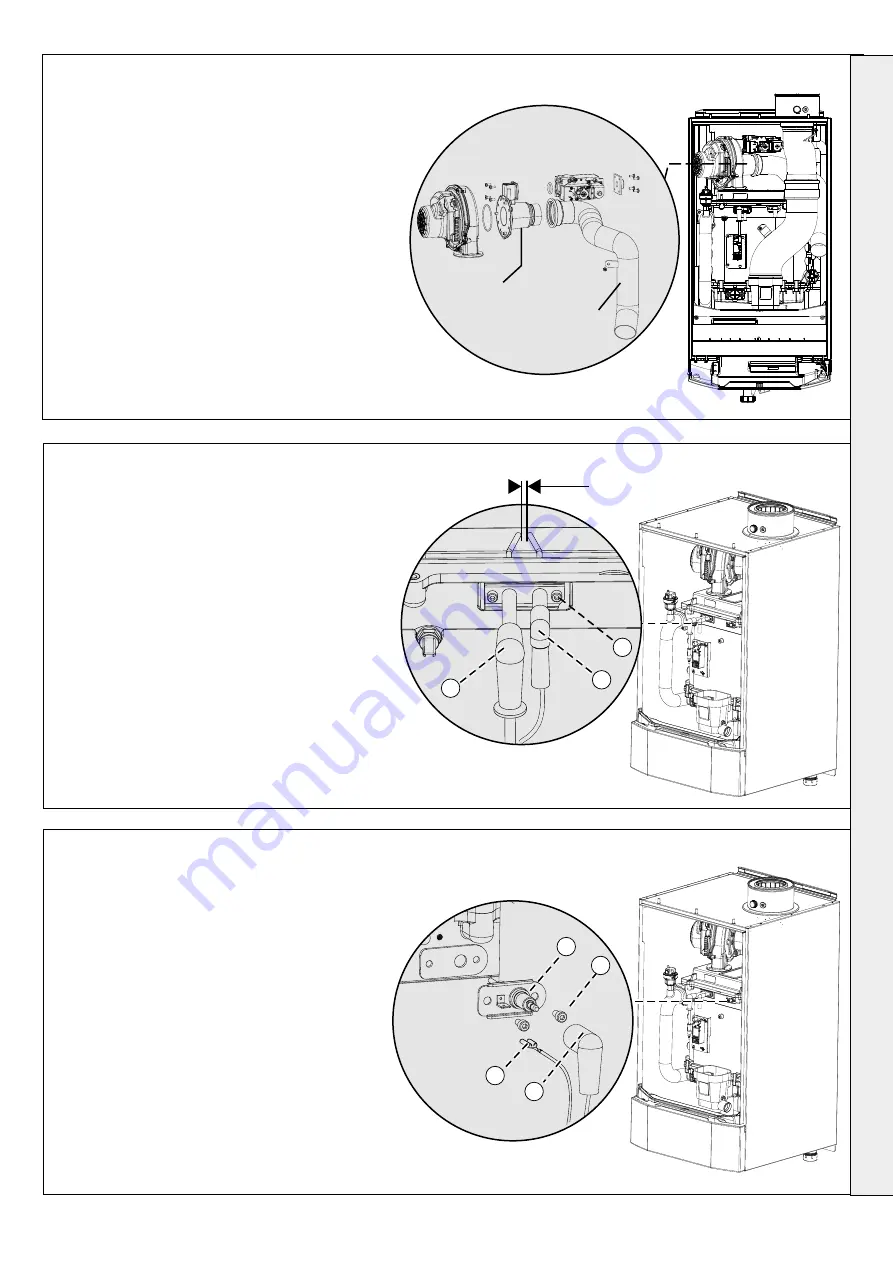
REMOVAL OF VENTURI / AIR INLET DAMPER
1. Refer to Section 2.33.
2. Remove the front panel. Refer to Section 3.2.
3. Remove the flue manifold complete with seal and
remove the air damper Section (all but the 150kW
have a fixing screw) refer to Section 3.4. If the air
inlet damper is damaged go to points 6-8.
4. Remove the fan and gas assembly. Refer to Section
3.3.
5. Remove venturi from fan and gas valve. Refer to
Sections 3.9 & 3.10.
6. Replace with new venturi/ air inlet damper if
necessary ensuring the gas orifice is fitted and seal
is replaced.
7. Reassemble in reverse order replacing all gaskets.
8. Check the operation of the boiler. Refer to Section
2.33
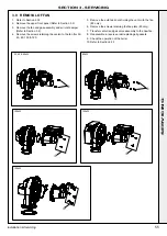
3.13 REMOVAL OF DETECTION ELECTRODE
1. Refer to Section 2.33.
2. Remove the front panel. Refer to Section 3.2.
3. Pull off the spark lead and earth connection.
4. Remove the two retaining cap head screws.
5. Pull out the electrode and pull off the old gasket.
6. Replace with new electrode and gasket supplied
checking the spark gap is 3.5mm ±1.
7. Reassemble in reverse order.
8. Check the operation of the boiler (Refer to
Section 2.33.
1. Refer to Section 2.33.
2. Remove the front panel. Refer to Section 3.2.
3. Pull off the detection lead and earth connection.
4. Remove the two retaining cap head screws.
5. Pull out the electrode and pull off the old gasket.
6. Replace with new electrode and gasket ensuring
correct electrode is fitted.
7. Reassemble in reverse order.
8. Check the operation of the boiler. Refer to
Section 2.33.
3.12 REMOVAL OF IGNITION ELECTRODE
3.5mm ±1
3
5
4
3
3
5
4
Air inlet damper
Venturi
57
Installation & Servicing
SECTION 3 - SERVICING
SER
VICING
Содержание EVOMAX 2 30
Страница 4: ...4 Installation Servicing...
Страница 75: ...75 Installation Servicing NOTES...
Страница 76: ...76 Installation Servicing NOTES...
Страница 77: ...77 Installation Servicing NOTES...
Страница 78: ...78 Installation Servicing NOTES...
Страница 79: ...79 Installation Servicing NOTES...

