ima5355
boundary
boundary
J
H
L
F
I
G
I
A
B
C
D, E
F
F
K
M
N
RF9807
A
A
B
A
A = 600mm
B = 2000mm
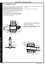
The flue terminal shall not
penetrate the shaded area
of the roof
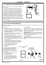
Due to the high efficiency of these boilers pluming will occur. For this reason vertical termination is recommended, and in any
case, terminal positions which could cause problems should where possible be avoided.
Particular care should be taken in the case of large multiple boiler installations, and complying with the requirements of the Clean Air Act.
The information below is extracted from BS. 5440 Pt. 1 and is for boilers with heat inputs not exceeding 70kW nett, and the latest
Building Regulation Part J. Detailed reference should still be made to these standards. In IE refer to I.S. 813:2002.
HEAT INPUTS IN EXCESS OF 70kW NETT
For boiler installations with total heat inputs in excess of 70kW nett, reference should be made to BS6644 and IGEM/UP/10. In IE refer
to I.S.820.2000.
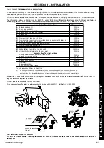
Concentric Wall Terminal Positions
Below an opening (1)
Above an opening (1)
Horizontally to an opening (1)
Below gutters, soil pipes or drain pipes
Below eves
Below balcony or car port roof
From a vertical drain pipe or soil pipe
From an internal or external corner or to a boundary alongside the terminal
Above ground, roof or balcony level
From a surface or a boundary facing the terminal
From a terminal facing the terminal
From an opening in the car port into the building
Vertically from a terminal on the same wall
Horizontally from a terminal on the same wall
300 mm
300 mm
300 mm
75 mm
200 mm
200 mm
150 mm
300 mm
300 mm
600 mm
1200 mm
1200 mm
1500 mm
300 mm
300 mm
500 mm*
500 mm*
500 mm
1000 mm
2000 mm
600 mm
A.
B.
C.
D.
E.
F.
G.
H.
I.
J.
K.
L.
M.
N.
Minimum spacing
Concentric Roof Terminal Positions
Directly below an opening, air brick, windows, etc.
Below plastic/painted gutters
Below painted surface
Below eaves or balcony
From wall
Below velux window
Above or side of velux window
* may be reduced to 300mm if a shield fitted
(1)
An opening here means an openable element, such as a openable window, or a fixed opening such as an
air vent. However, in addition, the outlet should not be nearer than 150mm (fanned draught) to an opening
into the building fabric formed for the purpose of accommodating a built in element, such as a window frame.
If the terminal is fitted less than 500 mm below plastic gutters, painted eaves or any other painted surface then an aluminium shield at least 1m
long should be fitted to protect the surface.
Vertical terminals must be a minimum of 550mm apart.
For positioning of open flue terminals reference should be made to BS. 5440 Pt. 1. In IE refer to I.S.813.2002.
2.17 FLUE TERMINATION POSITION
23
Installation & Servicing
SECTION 2 - INSTALLATION
FLUE OUTLET
Содержание EVOMAX 2 30
Страница 4: ...4 Installation Servicing...
Страница 75: ...75 Installation Servicing NOTES...
Страница 76: ...76 Installation Servicing NOTES...
Страница 77: ...77 Installation Servicing NOTES...
Страница 78: ...78 Installation Servicing NOTES...
Страница 79: ...79 Installation Servicing NOTES...


