Concord CX -
Installation
7
GENERAL
Particular reference should be made to BS. 6644:
Section 2; Subsection 10 and Guidance note PM5
"Automatically controlled steam and hot water boilers"
published by the Health and Safety Executive.
The information and guidance given below is not
intended to override any requirements of either of the
above publications or the requirements of the local
authority, gas or water undertakings.
Other British Standards applicable are BS.5422 and
BS.6700.
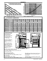
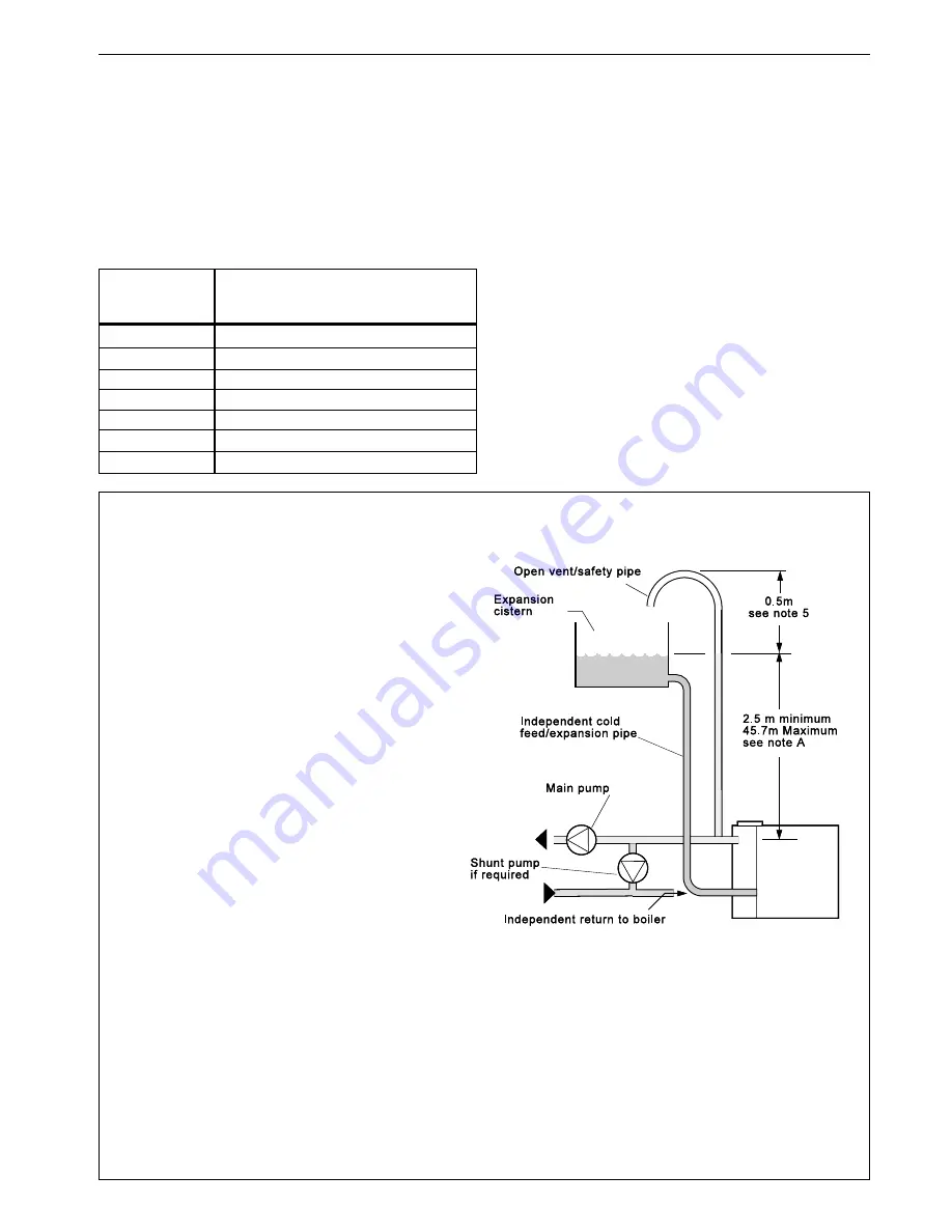
The information provided is based on the following
assumptions:
1.
An independent open vent/safety pipe connection is
made to the redundant boiler flow tapping or is
positioned immediately after the system flow pipe
connection to the header, as shown.
2.
An independent cold feed/expansion pipe connection
is made to the redundant boiler return tapping. Cold
feed/expansion pipe connections made to the
pumped system return will result in an increase in the
static head requirement, caused by the additional
resistance of the distributor tube. Surging may also
increase.
3.
The maximum flow rate through the boiler is based
on a temperature difference of 11 °C at full boiler
output and the circulating pump is positioned in the
flow to the system.
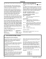
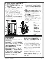
Note A.
This minimum height must be
increased, if necessary, to comply with the
minimum head required by the pump
manufacturer in order to avoid cavitation.
Note B.
This diagram does not show safety
valves, water flow switches, etc., necessary
for the safe operation of the system.
4.
The boiler is at the highest point of circulation in the system.
Systems designed to rise above the boiler flow tappings will
automatically require a minimum static head higher than that shown.
5.
The position of the open vent/safety pipe above the expansion
cistern water level is given as a guide only. The final position will
depend upon the particular characteristics of the system. Pumping
over of water into the expansion cistern must be avoided.
achieved either by provision of an adequate bypass circuit or
by ensuring that a zone of suitable size is open for
circulation during this period by relevant control of zone
valves or pumps.
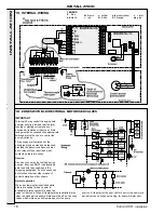
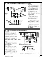
The wiring diagrams in Frames 16,17 &18 illustrate the
control methods for achieving the above.
3.
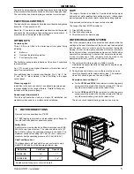
Pump selection should take account of the hydraulic
resistance given in Graph 2.
PUMP POSITIONS
Whenever practically possible the circulating pump(s) should be
positioned so that it pressurises the system being served. The
vertical distance between the pump(s) and any cold feed and
expansion cistern MUST comply with the pump manufacturers
requirements in order to avoid cavitation. These requirements
override the information given in Frame 3 if the static head required
for the pump(s) exceeds that required for the boiler.
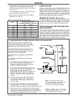
MINIMUM FLOW OF WATER - Refer to Table 4
The system design must provide for an adequate flow rate through
the boiler at all times when the boiler is firing. The minimum flow
rate should correspond to a temperature difference across the boiler
flow and return of 35
o
C (63
o
F), assessed at catalogue rating.
3 OPEN VENTED SYSTEMS - Minimum static head requirements
WATER TREATMENT FOR HOT WATER AND
HEATING BOILERS
There is a basic need to treat the water contained in all heating
and indirect water systems, particularly open vented systems. It is
assumed, incorrectly, that because boilers are operating in
conjunction with what is apparently a closed circuit an open vented
system will not, under normal circumstances, allow damage or
loss of efficiency due to hardness salts and corrosion once the
initial charge of water has been heated up a few times.
Table 4 - Flow rates for fully pumped systems
Boiler
Minimum flow rates for a
temperature difference of 35
0
C (63
0
F)
l/s
g.p.m.
CX 40
0.28
3.7
CX 50
0.34
4.5
CX 60
0.41
5.4
CX 70
0.48
6.3
CX 80
0.55
7.3
CX 90
0.62
8.2
CX100
0.68
9
Содержание Concord CX40
Страница 1: ......


