INSTALLATION
8
Harrier GT Range
- Installation
6
OIL OR GAS CONNECTION
See specific technical information supplied with the burner.
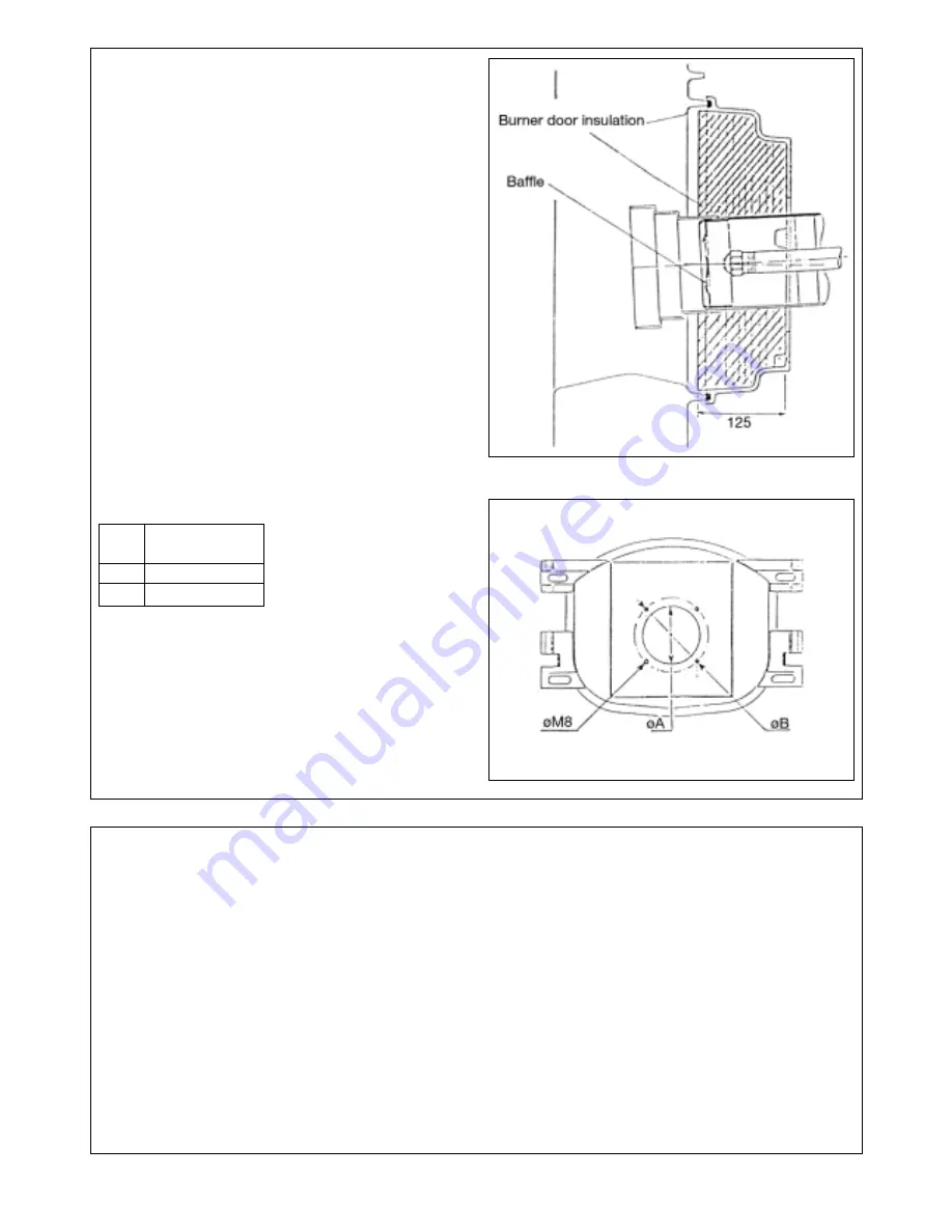
Burner positioning
Caution: the baffle at the head of the burner must be in line
with the burner door insulation level.
GAS SUPPLY
The gas supply MUST be sized in accordance with British
Gas recommendations and be fabricated in compliance with
CP.331 Pt. 3 and any Local Gas Board installation standards.
The Local Gas Board should be contacted, at a stage prior to
actual insallation, for any advice or information required.
Details and advice, relating to the use of L.PG. for firing the
IDEAL HARRIER GT range of heating boilers, are available on
request to Caradon Ideal Ltd.
OIL STORAGE TANK
The oil storage tank, oil supply pipe and connections to the
burner unit MUST comply with the requirements of BS. 779
and CP.541 0.
The installation should conform to the recognised standards
of good practice in the trade and comply with the relevant
Codes of Practice, Building Regulations and Local Authority,
Fire and insurance requirements.
8219-EN-22
8219-EN-61
Drilling ø for burner door:
Harrier GT
5 to 9 sections
ø A
135
ø B
170
7
ELECTRICAL CONNECTIONS TO THE CONTROL PANEL
CAUTION: The connection must be carried out by a
qualified professional.
As the electrical wiring has been carefully checked in the
factory, the internal connections of the control panel must
not be modified under any circumstances.
The electrical connections of the boiler must conform with
the lEE wiring regulations in force and with the specifications
shown on the electrical drawings provided with the
equipment, and the directions given below. The equipment
should be supplied by a circuit using an omnipolar circuit
breaker with an opening gap greater than 3 mm.
Содержание Harrier GT
Страница 38: ...38 Harrier GT Range Installation NOTES ...
Страница 39: ...Harrier GT Range Installation 39 NOTES ...


