background image

Installation

iMAT 31IFBI-24VDC

11

Installation instructions:

• Only the displayed installation position of the iMAT

(3) is permissible. Never install in a horizontal or
any other tilted position.

• Feed pipe (1) and ball valve (2) at least G½.
• No filter or screen in the inlet line.
• Slope in the inlet line >1%.
• Use ball valves (2) only.
• Operating pressure: min. 0,8/1,2 bar (12/17 psig),

max. 16 bar (230 psig). See type plate.

• Short pressure hose

(4)

fixed on a pressure-

resistant pipe.

• The required minimum pressure increases by

0,1 bar (1,4 psi) per metre gradient in the
discharge pipe (5).

• Discharge pipe (5) rising by max. 5 m (16,4ft).
• Install manifold (6) ½" with a slope of 1%.
• Introduce the discharge pipe (5) from the top into

the manifold (6).

• Prior to the start-up, always carry out a leak test

and verify the correct engagement of the control
unit.

Содержание IMAT 31IFBI-24VDC

Страница 1: ...EN US english US Instructions for installation and operation Condensate drain MAT 31IFBI 24VDC 01 2783 ...

Страница 2: ... read the installation and operating instructions carefully before mounting and starting up the iMAT 31IFBI 24VDC and follow our directions Perfect functioning of the iMAT 31IFBI 24VDC and thus reliable condensate discharge can only be guaranteed when the provisions and notes stipulated here are strictly adhered to ...

Страница 3: ...usion from the scope of application 6 5 Technical data 7 6 Electrical data 7 7 Dimension drawing 8 8 Function 9 9 Installation 10 10 Electrical installation 13 11 Control and maintenance 15 12 Troubleshooting and fault elimination 18 13 Elements and components 19 14 Recommended spare parts 19 ...

Страница 4: ...Therefore it is imperative for the service technician and the responsible operator technical staff to read these operating instructions prior to installation start up and maintenance The operating instructions must be accessible at any time at the place of application of the iMAT 31IFBI 24VDC In addition to these operating instructions local or national regulations must be complied with if necessa...

Страница 5: ...rench size SW27 as a back rest The service unit must not be dismantled Pos 12 Beko Technische D okumentati on Sicher hei t Vorsicht Fehlfunktion 0 mod_1214378096290_15098 docx 15237 1 Caution Malfunction during operation Through incorrect installation and poor maintenance malfunction may occur at the iMAT Condensate which is not discharged may cause damage to plants and in production processes Pos...

Страница 6: ...uring the entire operating time Pos 17 Beko Technische D okumentati on Überschriften 1 Ausschluss vom Anwendungsber eich 0 mod_1236003439359_15098 docx 15308 1 1 4 Exclusion from the scope of application Pos 18 Beko Technische D okumentati on Besti mmungsgemäße Ver wendung BEKOM AT Ausschl uß Anwendung BM 31 32 33 U 0 mod_1236003837511_15098 docx 15309 1 The iMAT 31IFBI 24VDC as a condensate drain...

Страница 7: ...s of CAN CSA C22 2 No 61010 1 12 third edition including a later version of the same standard incorporating the same level of testing requirements Pos 24 Seitenumbr uch 0 mod_1157028099015_0 docx 15320 1 Pos 25 Beko Technische D okumentati on Überschriften 1 Elektrische D aten 0 mod_1183638451371_15098 docx 15115 1 1 6 Electrical data Pos 26 Beko Technische D okumentati on El ektrische Daten BEKOM...

Страница 8: ...entati on Überschriften 1M aßzei chnung 0 mod_1183638072605_15098 docx 15109 1 1 7 Dimension drawing Pos 29 Beko Technische D okumentati on Technische D aten M asszeichnung 0 mod_1184569815280_15098 docx 15135 1 Pos 30 Seitenumbr uch 0 mod_1157028099015_0 docx 15320 1 ...

Страница 9: ...lates in the housing 2 A capacitively functioning sensor 3 continuously registers the filling level and releases a signal to the electronic interface output Sen as soon as the container is filled See also Chapter Electrical installation The pilot valve 4 is triggered by an external signal input Drn When this signal is available the valve is activated and the membrane 5 opens the outlet line 6 to d...

Страница 10: ...hmen Fehl funkti onen BM 0 mod_1214378434025_15098 docx 15238 1 r Measures Condensate drainage which is reliable in performance directly optimizes the compressed air quality To prevent damage and breakdowns it is imperative to observe the following Exact compliance with the specifications of use and with the performance parameters of the iMAT in connection with the case of application see Proper u...

Страница 11: ... valves 2 only Operating pressure min 0 8 1 2 bar 12 17 psig max 16 bar 230 psig See type plate Short pressure hose 4 fixed on a pressure resistant pipe The required minimum pressure increases by 0 1 bar 1 4 psi per metre gradient in the discharge pipe 5 Discharge pipe 5 rising by max 5 m 16 4ft Install manifold 6 with a slope of 1 Introduce the discharge pipe 5 from the top into the manifold 6 Pr...

Страница 12: ...id a water pocket when installing the feed pipe Deflector area If drainage is to be carried out directly from the pipe deflection of the air flow will be useful Ventilation If the slope in the inlet line is not sufficient or if any other inflow problems occur a venting line needs to be installed Pos 41 Seitenumbr uch 0 mod_1157028099015_0 docx 15320 1 ...

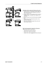
Страница 13: ...d remove upper part of the cover 2 5 Unscrew the threaded cable connection 3 if there is one remove the plug and lead the cable 4 for the supply voltage through 6 Connect the cable 4 with the terminals 5 7 Install the cables as shown see also terminal assignment in the following text 8 Tighten the threaded cable connection 3 with a slightly sealing effect 9 Put on the upper part of the cover 2 and...

Страница 14: ...nsor covered Gnd supply voltage 0 V mass DC Only Input w Pull Up Output Open Drain 0 V Mass 1 1 1 2 1 3 1 4 Note Between the terminals and the housing or the condensate connections there is no galvanic isolation The provided 24 VDC voltage must comply with the requirements for protective extra low voltages PELV in accordance with IEC 60364 4 41 Tighten the threaded cable connection with a slightly...

Страница 15: ...hat persons or objects cannot be hit by condensate or escaping compressed air Pos 50 Beko Technische D okumentati on Sicher hei t Vorsicht Fehlfunktion 0 mod_1214378096290_15098 docx 15237 1 Caution Malfunction during operation Through incorrect installation and poor maintenance malfunction may occur at the iMAT Condensate which is not discharged may cause damage to plants and in production proces...

Страница 16: ...should be avoided Condensate is subject to mandatory waste disposal As such it must be collected in suitable containers and disposed of or processed properly Pos 54 Beko Technische D okumentati on Wartung BEKOM AT Wartung BM 31U 32U IF built in 8000h 6 mod_1375435388721_15098 docx 33087 1 Maintenance recommendation Replace the service unit 5 after 8 000 operating hours or max one year 1 Remove the...

Страница 17: ...lean dry and free from impurities 3 Introduce the sensor 12 into the sensor tube plate 14 4 Hang the hook 15 of the control unit 1 in the sensor tube plate 14 5 Press the control unit 1 against the service unit 5 and snap into place Start up subsequent to maintenance measures Always carry out prior to the start up Leak test of the screwed connector Check of the electrical connections Check of the ...

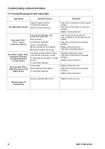
Страница 18: ...ar Circuit board defective Service unit defective Minimum pressure not reached Maximum pressure exceeded Check feed and discharge pipe Check whether or not the valve opens audibly Check the circuit board for possible damage Replace the circuit board Check the operating pressure No sensor signal Sen transistor switched Gnd potential with covered sensor Feed pipe without sufficient slope Cross secti...

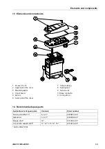
Страница 19: ...8 docx 15111 1 1 14 Recommended spare parts Pos 63 Beko Technische D okumentati on Ersatzteile Verbr auchsmaterialien Zubehör BEKOMAT Ersatzteil e IC P 31 BM 31U USA FKM N PT 9 mod_1415014956472_15098 docx 42420 1 Available sets of spare parts Contents Order number Service Unit iMAT 31 8 9 11 4028457 ICP Gasket kit 3 8 11 4024386 ICP Design shell 16 4010164 ICP Connection adapter NPT 11 12 13 14 1...

Страница 20: ...or 19 I Inlet line 9 Installation 10 Installation and operating instructions 4 Installations und Betriebsanleitung 4 Instructions safety instructions 4 L Lower part of the cover 19 M Maintenance 15 Maintenance recommendation 16 Malfunction 18 Membrane 9 Mounting 10 N No condensate discharge 18 No function 18 No sensor signal 18 O Order number 19 Outlet line 9 P Piktogramme 4 Pilot valve 9 Pressure...

Страница 21: ...iMAT 31IFBI 24VDC 21 ...

Страница 22: ...22 iMAT 31IFBI 24VDC ...

Страница 23: ...iMAT 31IFBI 24VDC 23 ...

Страница 24: ... 206 Jeffersonville IN 47131 www icompressorpartners com Translation of the original manual instructions Original instructions are in German Subject to technical modifications without notice errors accepted ICP_iMAT31_IF_BI_manual_en_us_2014_12 Printed in Germany ...

Отзывы: