background image

14

INSTALLATION AND CONNECTIONS

54


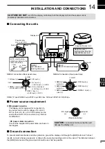
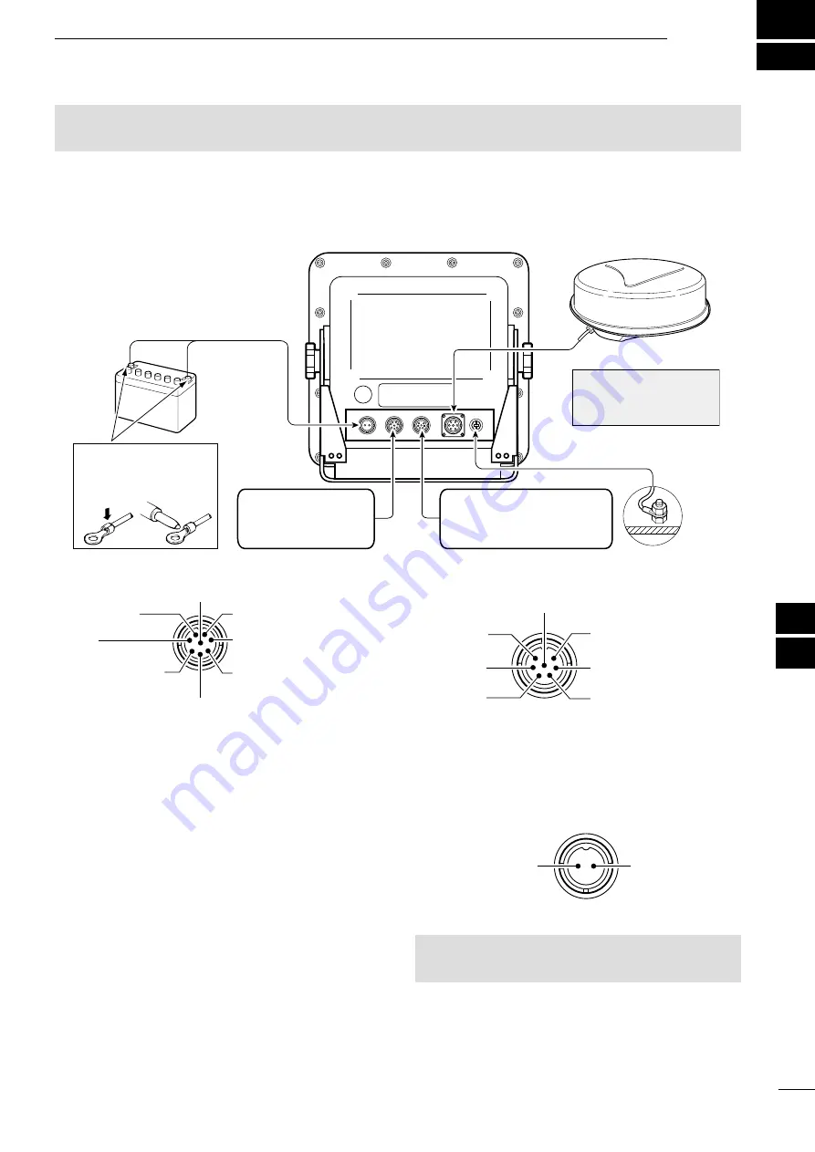
Connecting the units

NMEA2:

NMEA 0183 data input/output

+

Ground

Power supply

10.2 to 42 V DC

Red:

Black: 

_

PWR

GND

NEVER connect 

anything other than the 

supplied Scanner unit.

Supplied Scanner unit

Display unit

NOTE: Use the termi-

nals shown below for the 

cable connections.

Solder

Crimp

NMEA1:

AIS data input

Bearing data input

NMEA 1/2 inputs/NMEA 2 output/DSC input: 4800 bps, AIS input: IEC61162-2 38400 bps


Ground connection

To prevent electrical shocks and other problems, ground the display unit through the [GND] terminal. For best 

results, connect a heavy gauge wire or strap to the nearest grounding point on the vessel

. The distance between 

the [GND] terminal and the ground point should be as short as possible.


Power source requirement


D

DC power source

   The display unit is designed for connection to 

any power source with a voltage of 

10.2–42 V 

DC, so that a 12, 24, or 32 V DC battery can be 

used without a DC-DC converter or any internal 

modifications. 

 • 

DC power cable connection

   Connect the supplied DC power cable as shown in 

the diagram.

(Rear panel view)

DC input

(+)

Ground

(–)

CAUTION

:


An incorrect cable connection will 

damage the display unit.

NMEA1 connection (Rear panel view)

q

 AIS input (+)

w

 NC

i

 GND

r

 NMEA 1 input (–)

    or AUX input (–); DATA

e

 NMEA 1 input (+)

     or AUX input (+); DATA 

u

 AIS input (–)

y

 N+1 input (–)

     or AUX input (–); CLOCK

t

 N+1(+); data input

     or AUX input (+); CLOCK

NMEA2 connection (Rear panel view)

q


NMEA 2

     output (+)

w


NMEA 2

     output (–)

e


NMEA 2

     input (+)

u


GND

y


DSC input (–)

t


DSC input (+)

r


NMEA 2  input (–)

1
2
3
4
5
6
7
8
9
10
11
12
13
14
15
16
17
18
19
20
21

CAUTION!


DO NOT


turn ON the display unit before both the display unit and the scanner unit is 

completely installed and connected.

Содержание MR-1010RII

Страница 1: ...MR 1010R MARINE RADAR INSTRUCTION MANUAL...

Страница 2: ...9 Installation nuts M6 5 10 Spring washers M6 10 11 Flat washers M6 10 12 Instruction manual 1 13 Operating guide 1 14 EX 2714 template 1 15 Display unit template 1 z z Scanner unit EX 2714 Quantity 1...

Страница 3: ...the Icom logo are registered trademarks of Icom Incorporated Japan in Japan the United States the United Kingdom Germany France Spain Russia Australia New Zealand and or other countries BE CAREFUL SA...

Страница 4: ...eets IPX4 requirements for splash resistance when the supplied connection cable scanner unit are connected However if it is dropped splash resistance cannot be guaranteed because of possible damage to...

Страница 5: ...late MR 1010RII OPERATING GUIDE SYSTEM COMPONENTS i SUPPLIED ACCESSORIES i IMPORTANT ii FEATURES ii EXPLICIT DEFINITIONS ii PRECAUTIONS iii 1 PANEL DESCRIPTIONS 1 6 Front panel 1 Screen 3 2 BASIC OPER...

Страница 6: ...t or u to select the Menu group or push p or q to select the menu items in the Menu screen p 39 y ENTER KEY Described as ENTER in this manual Push to select the target and display the ARPA AIS DSC TL...

Страница 7: ...EBL1 and the VRM1 EBL Electronic Bearing Line VRM Variable Range Marker Push t or u to adjust the EBL selector or push p or q to adjust the VRM selector Then push ENTER to set the point The EBL1 bear...

Страница 8: ...ta rHEADING INDICATOR p 15 Displays the heading readout The HDG readout indicates the bow of the ship s heading in a clockwise direction from north Indicator Description HDG Displayed when the Bearing...

Страница 9: ...n or kilometers km h can be selected as the speed unit in the Initial menu 8INFORMATION BOX pp 14 23 26 32 Displays a detailed information of a selected target such as AIS ARPA TLL Waypoint or DSC L L...

Страница 10: ...KER p 14 Displays a waypoint that is received from navigation equipment This marker is displayed when the WPT Display item in the Display menu is set to ON To display the Waypoint marker bearing data...

Страница 11: ...ounds in case such as a vessel is entered into the zone that you have set Push CLEAR key to stop the alarm sound and close the displayed message 8POPUP MESSAGE p 32 A message pops up when the radar re...

Страница 12: ...ush p or q to select a language and push ENTER p 38 Turning OFF the power z z Push to turn OFF the power Basic operation 1 Turn ON the power q Standby indicator is displayed after the Warm up is compl...

Страница 13: ...open the Brilliance Color box 2 Push q twice to select the Color item 3 Push t or u to select a display color L L You can set the display color to the Day Night or User 4 Push CLEAR to close the box...

Страница 14: ...anked Small objects may not be displayed on the screen when strong echoes from rain or islands within 1 NM while the automatic SEA function is activated D DRAIN function This function eliminates echoe...

Страница 15: ...times normal view 1 Move the cross line cursor to a desired target 2 Hold down MODE for 1 second to toggle between the zoomed view and the normal view The ZOOM icon is displayed in the upper right of...

Страница 16: ...tion during normal operation Long pulse function To magnify the blips for easier viewing of small targets the long pulse and echo stretch functions are usable When the long pulse is used in the 3 4 to...

Страница 17: ...p or q to select an item L L The selectable settings are described below 4 Push ENTER to enter the option selection mode 5 Push t or u to select an option 6 Push ENTER to save the setting 7 Push MENU...

Страница 18: ...setting 7 Push MENU to exit the Menu screen D DEntering the power saving mode 1 Hold down TX SAVE for 1 second to enter the power save mode The SAVE indicator is displayed in the upper right of the s...

Страница 19: ...in NMEA 0183 format is applied the radar can display the waypoint To display the waypoint marker bearing data and position data are required p 53 D DDisplaying the waypoint marker 1 Push MENU 2 Push t...

Страница 20: ...urse Over the Ground data as the bearing However if the vessel s speed is less than 3 knots direction accuracy falls Moreover the position accuracy or the current actual course may vary therefore the...

Страница 21: ...ion is selected in step 4 push q to select the Manual Variation then push ENTER 8 Push p or q to set the bearing variation 9 Push ENTER to save the setting 10 Push MENU to exit the Menu screen NOTE NM...

Страница 22: ...he fixed rings MENU w Initial w Range Ring 1 Push MENU 2 Push t or u to select the Initial menu 3 Push p or q Select the Range Ring item 4 Push ENTER to enter the option selection mode 5 Push t or u t...

Страница 23: ...h EBL1 VRM1 to display the EBL1 and VRM1 Push t or u to rotate the Electronic Bearing Line Push p or q to increase or decrease the Variable Range Marker s ring size The EBL VRM1 readout indicates the...

Страница 24: ...nd then set the VRM1 and EBL1 to a previously plotted target L L Push t or u to rotate the Electronic Bearing Line L L Push p or q to increase or decrease the Variable Range Marker ring size 3 Push EN...

Страница 25: ...VRM2 to display the EBL2 and VRM2 and then set the VRM2 and EBL2 to a target point for example a next waypoint The intersection of the EBL1 and VRM1 becomes the center of the EBL2 and VRM2 5 The VRM2...

Страница 26: ...elected alarm zone is displayed 6 Push ALM1 2 1 2 to set the alarm zone and activate the alarm function The Alarm icon is displayed The selected alarm zone remains 7 If a target comes into or goes out...

Страница 27: ...t or u to select the System menu 2 Push p or q to select the Zone Alarm1 or Zone Alarm2 item 3 Push ENTER to enter the option selection mode 4 Push t or u to select IN or OUT IN Alarm sounds when the...

Страница 28: ...and direction defined by the calculated true or relative course and speed The vector line is displayed on the target ARPA operation D DOperation Select a target on the screen that you want to track 1...

Страница 29: ...le icon changes to a circle and the vector of the vessel is displayed 5 Target with a number Displayed when the No Display setting in the ARPA menu in the Menu screen is set to Select or all CPA TCPA...

Страница 30: ...et menu OFF Turns OFF the Track display function ON Turns ON the Track display function No Display Default Select Select the target identification number type that appears at the right side of the mar...

Страница 31: ...31 1 Move the cross line cursor onto a desired target 2 Push ENTER to select the target The corners of a square appear on the selected target and the target information appear in the AIS information b...

Страница 32: ...standby screen when a valid VDM sentence is input from the NMEA1 AIS port L L The AIS target icons are displayed when AIS is selected in the STBY Mode item of the System menu p 31 If more than the sp...

Страница 33: ...d target The target is displayed with the heading line SOG Speed Over Ground COG Course Over Ground vector and ROT Rate of Turn ROT Rate of Turn SOG Speed Over Ground and COG Course Over Ground vector...

Страница 34: ...Activate Distance Default 1 0NM Sets the distance from your vessel to between 0 1 and 10 0 NM to automatically turn the sleeping AIS target into an activated target Auto Activate Angle Default 180 Se...

Страница 35: ...faster than 2 knots 3 min 3 min 18 min 18 min 2 Vessel is at anchor or moored and moving faster than 3 knot 10 sec 60 sec N A 4 N A 4 3 Class A Vessel is moving between 0 and 14 knots 10 sec 60 sec C...

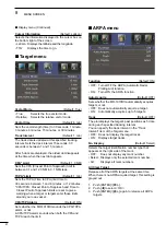
Страница 36: ...3 vessels as your favorite AIS targets Related settings D DTarget menu You can change the target settings for the AIS operation The settings of the Target menu are commonly used for the ARPA and AIS o...

Страница 37: ...re displayed z z Hold down ENTER for 1 second to display the detailed information or push CLEAR to close the message box Also the alarm stops L L Push CLEAR to close the DSC details message D DDSC set...

Страница 38: ...target identification number position bearing BRG distance DIST Time to go TTG and day time Day Time are displayed L L To close the information box move the cursor to anywhere there is no mark then pu...

Страница 39: ...lect the language You can select a language of the menus messages indicators and so on The selectable language differs depending on the version of your display unit 1 Push MENU to display the Menu scr...

Страница 40: ...ush ENTER to enter the option selection mode 8 Push t or u to adjust the echo until it becomes straight See below 9 Push ENTER to save the setting 10 Push MENU to exit the Menu screen Proper adjustmen...

Страница 41: ...AVE to display the target on the screen 3 Push MENU to display the Menu screen 4 Push t or u to select the Initial menu 5 Push p or q to select the Heading Adjust item 6 Push ENTER to enter the option...

Страница 42: ...change from one to another The save or load settings are the settings of the items in the Color Trail Display Target ATA AIS Video and System menus L L Save settings and Load settings are selectable...

Страница 43: ...this case 4 Push ENTER to enter the option selection mode 5 Push t or u to select OK 6 Push ENTER to reset the settings 7 Push MENU to exit the Menu screen D DFactory Reset 1 Push MENU to display the...

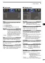
Страница 44: ...e Brilliance of the ARPA and AIS symbols to 1 dark 2 normal or 3 bright ARPA Automatic Radar Plotting Aid AIS Automatic Identification System EBL VRM PI Brill Default 3 Sets the Brilliance of the EBL...

Страница 45: ...vector ON Displays your own ship s vector Bearing data and ship speed are required PPI Area Default Wide Selects the PPI Plan Position Indicator area Normal The PPI area is inside the scale Wide The...

Страница 46: ...en a target or targets enter those limits around your own vessel CPA TCPA Alarm Default ON Sets whether the MR 1010RII sounds the CPA TCPA alarm or not A CPA TCPA alarm sounds when both the CPA and TC...

Страница 47: ...om your vessel Auto Activate Angle Default 180 Sets the angle to automatically change the sleeping AIS target to an activated target 5 to 180 Select the angle with your vessel New Target Warning Defau...

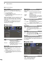
Страница 48: ...e adjustment mode Dynamic Range Default Narrow Selects the dynamic range of the Plan Position Indicator PPI Narrow Narrow dynamic range Even weak reflections are displayed as strong reflections Middle...

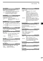
Страница 49: ...isplayed bearing type regardless of the bearing data format NMEA N 1 AUX or GPS True True North bearing Magnetic Magnetic North bearing Variation Default Auto Selects the difference setting between tr...

Страница 50: ...may not match with other HDG format and includes errors L L When a Vessel s speed is less than 2 knots the direction information is not displayed until the speed increases to more than 3 knots GPS L...

Страница 51: ...isplays own AIS information Status menu Displays the status of the GPS Heading AIS and DSC inputs alarm settings number of acquirable ARPA and CPA TCPA alarm settings L L The ARPA indicates the remain...

Страница 52: ...eam inside the sidelobes If a target reflects this radiation it will be displayed on the screen as an echo Main beam Sidelobes Sidelobe echoes usually occur at short ranges and as a result of large st...

Страница 53: ...too high off the water because the bottom of the vertical beam of the scanner overshoots nearby targets This target cannot be detected by radar The target in this area cannot be detected Pulse length...

Страница 54: ...e width they appear as two echoes When two targets are not separated by more than the pulse width they appear as 1 echo Transmit pulse Echoes Target 1 Target 2 Target 2 Target 1 Transmit pulse Echo Ta...

Страница 55: ...tend to dim the picture 1 Wipe the surface of the display unit with a clean soft cloth DO NOT use harsh solvents such as Benzine or alcohol 2 If the picture is still dim clean the LCD screen Scanner...

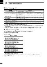
Страница 56: ...ed for more than 15 seconds an alarm sounds 1 Turn OFF the power then check the system cable connections 2 Push any key to cancel the error message and beep tone Turn OFF the power then check the exte...

Страница 57: ...m Beam width typical Horizontal beam 4 Vertical beam 22 Side lobe typical 22 dB Polarization Horizontal Transmission frequency 9410 MHz 30 MHz P0N Peak output power 4 kW Pulse width 80 ns 2160 Hz 80 n...

Страница 58: ...m status 3 ALR DSC DSC Required RMC GGA GLL or GNS DSC DSE EXTERNAL DATA OUTPUT NMEA2 1 connector RMC GGA GLL VTG TTM TLL RSD OSD 1 NMEA1 and NMEA2 connectors See page 54 2 AIS input also receives RMC...

Страница 59: ...e Power source requirement D DDC power source The display unit is designed for connection to any power source with a voltage of 10 2 42 V DC so that a 12 24 or 32 V DC battery can be used without a DC...

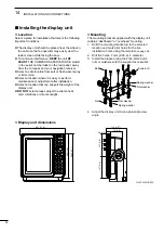
Страница 60: ...lt or fresh water spray or immersion z z Select a location where it is easy to perform maintenance or adjustment after installation z z Select a location that can support the weight of the display uni...

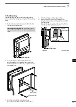
Страница 61: ...nstrument panel or wherever you plan to mount the display unit M6 mounting bolt Spring washer Flat washer 3 Drill four holes for the mounting screw L L The screw hole depth is 14 5 mm 9 16 inches 4 Sl...

Страница 62: ...ossible on the vessel to obtain best performance with maximum range If you install two or more radar in one vessel install one above and the other s below The mounting surface must be parallel with th...

Страница 63: ...ched near the sealing connector L L Be sure to clamp it tightly r 6 Connect the power cable black and red to the power connector t 7 Tighten the sealing nut then replace the radome cover over the scan...

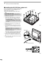
Страница 64: ...to remove the seal Otherwise you may injure your nail 2 Remove the 12 screws from the display unit s rear panel Fig 1 3 Slowly open the rear case and disconnect the four connectors from the display s...

Страница 65: ...bles 11 Adjust the video output cable length and then tighten the sealing nut Fig 6 UX 252 Video output cable Connector Connector Fig 4 UX 252 Ferrite EMI filter Cable tie Fig 5 Video output cable Sea...

Страница 66: ...n and connections 54 Installation checklist 59 IR function 10 K Keypad 1 L Language 34 Long pulse 4 M Maintenance 50 Manual speed 44 Manual tuning 9 Measurement 17 MENU screen 39 MODE key 1 7 N North...

Страница 67: ...99 8 mm 3 15 16 inch 199 6 mm 7 27 32 inch 256 mm 10 3 32 inch 7 mm d 1 4 inch d 7 mm d 2 1 4 inch d 31 mm 1 7 32 inch 62 mm 2 7 16 inch 92 mm 3 5 8 inch Display mounting bracket template Cut here...

Страница 68: ......

Страница 69: ...r 1 Heading indicator 7 8 Alarm zone Display information 1 North up and Course up screens can be used only when a bearing input NMEA N 1 or AUX is connected 2 AIS data is required 3 Your position data...

Страница 70: ...No Display All Clear Target AIS Display Track Name Display Auto Activate Auto Activate Distance Auto Activate Angle New Target Warning Display Range Number of AIS Slow Warn Slow Warn Speed Erase Lost...

Страница 71: ...MEMO...
Страница 72: ...A 7361D 1EX Printed in Japan 2017 Icom Inc Printed on recycled paper with soy ink 1 1 32 Kamiminami Hirano ku Osaka 547 0003 Japan...

Отзывы: