7
2
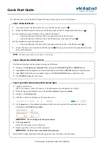
CONNECTION AND MAINTENANCE
Install the optional UT-109 and UT-110 as shown below:
q
Turn power OFF, then disconnect the DC power cable.
w
Unscrew the 4 screws, then remove the bottom cover.
e
Remove the unit pre-installed at the factory.
r
Cut the print pattern on the PCB at the TX mic circuit (A)
and RX AF circuit (B) as shown below.
t
Install the scrambler unit.
y
Replace the bottom cover and screws, then the DC power
cable.
NOTE:
Be sure to re-solder
the disconnected points at
left, otherwise no TX modu-
lation or AF output is avail-
able when you remove the
scrambler units.
B
■
Optional UT-109/UT-110 installation
Front panel
IC-F610_F620_F621-2.qxd 04.3.17 3:51 PM Page 7 (1,1)
Содержание IC-F620
Страница 1: ......
Страница 9: ...6 2 CONNECTION AND MAINTENANCE v s...
Страница 14: ......
Страница 15: ...MEMO...
Страница 16: ...1 1 32 Kamiminami Hirano ku Osaka 547 0003 Japan...