

Quick Start Guide
SD Transcoder - Quick Start Guide - P/N S16986 RA
1.
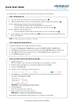
ASI output: connect the ASI cable to the rear of the SD encoder, on port 2
.
2.
Connect an Ethernet cable to the rear of the SD transcoder on eth0 for management and UI access
.
3.a.
For installations using IP outputs (with or without ASI output):
•
Connect an Ethernet cable from eth2 of the main transcoder to the IP switch.
•
Connect an Ethernet cable from eth2 of the SD transcoder to the same IP switch
3.b.
For installations using ASI outputs only:
•
Connect an Ethernet cable from eth2 of the main transcoder to eth2 of the SD transcoder
.
4.
Connect the power cord to the back of the SD encoder
. Plug the power cord into the grounded outlet, then
power up the appliance.
1
2
3
3
4
Step 1: Connections/Power
1.
Launch a web browser:
HTTP://{IP-Address}
where {IP-Address} is the Management network address set in Step 2.
2.
When the Login page displays, login with username
admin
and password
admin
.
3.
Navigate to the
Services
Page.
4.
Click the button to configure each Transcoder service:
5.
On the
Input
tab, set the multicast destination to that set on the output of the main transcode receiver.
The default is
239.0.95.99
port
5000
:
IMPORTANT:
Do not change any other parameters.
6.
Click
Save and Exit
.
Result: The transcoder service will restart.
7.
Repeat steps #4 to #6 for each of the transcoders.
IMPORTANT:
Set them to the same multicast destination.
Result: MPTS output containing all the SD programs is now available on the ASI output.
Step 3: Log in to the unit and set up the Transcoder inputs
The Ethernet interfaces can be configured using the LCD panel:
1.
Navigate to the
Main menu > Network
submenu using the
UP
,
DOWN
,
LEFT
and
RIGHT
buttons.
2.
Select
Eth0
for the Management network address then use the
UP
and
DOWN
buttons to adjust the value.
3.
Select
Eth2
for the Data network address then use the
UP
and
DOWN
buttons to adjust the value.
4.
Press
ENTER
to apply the new values.
Step 2: Configure the network interfaces
NOTE:
See back panel connector locations on next page.
The SD transcoder receives the MPTS output of the main transcoder receiver via IP multicast.


