2
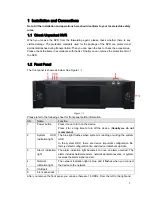
from the top to the bottom, it ranges from 1~4, 5~8, 6~12, 13~16.
You can see there are two indication lights on the HDD bracket.
z
The power indication light is at the top. The light is yellow after you connected the device to
the power.
z
The read-write indication light is at the bottom. The blue light flashes when system is
reading or writing the data.
1.3
Rear Panel
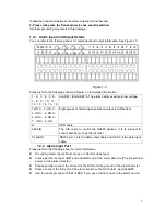
The rear panel is shown as below. See Figure 1-2.
Figure 1-2
Please refer to the following sheet for detailed information.
SN
Function
SN
Function
1
Power socket
6
Video VGA output
2
Audio Input
7
eSATA port
3
Audio output
8
USB port
4
Bidirectional talk input
9
HDMI port
5
Network port
10
Alarm input, alarm output, RS485 port.
1.4
Alarm Input and Output Connection
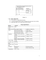
Please refer to the following sheet for alarm input and output connection.
There are two alarm input types for you to select: normal open (NO) and normal close (NC).
1. Alarm input
a. Please make sure alarm input mode is grounding alarm input.
b. Grounding signal is needed for alarm input.
c. Alarm input needs the low level voltage signal.
d. Alarm input mode can be either NC (normal Open) or NO (Normal Close)
e. When you are connecting two NVRs or you are connecting one NVR and one other device,
please use a relay to separate them.
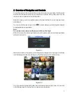
2. Alarm output
The alarm output port should not be connected to high power load directly (It shall be less than
1A) to avoid high current which may result in relay damage. Please use the co contactor to

