


v
Follow
the
suggested
actions
in
the
order
in
which
they
are
listed
in
the
Action
column
until
the
problem
is
solved.
v
See
to
determine
which
components
are
customer
replaceable
units
(CRU)
and
which
components
are
field
replaceable
units
(FRU).
v
If
an
action
step
is
preceded
by
“(Trained
service
technician
only)”,
that
step
must
be
performed
only
by
a
trained
service
technician.
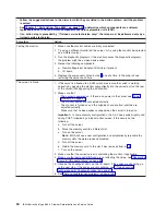
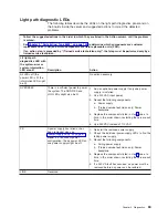
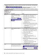
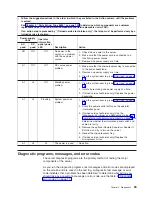
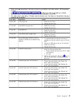
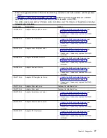
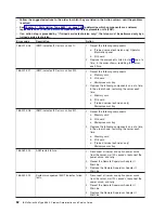
Lit
light
path
diagnostics
LED
with
the
system-error
or
system-information
LED
also
lit
Description
Action
FAN
A
fan
has
failed
or
has
been
removed.
Note:
A
failing
fan
can
also
cause
the
TEMP
LED
to
be
lit.
1.
Reinstall
the
removed
fan.
2.
If
an
individual
fan
LED
is
lit,
replace
the
fan.
3.
Reseat
the
microprocessor
tray.
4.
(Trained
service
technician
only)
Replace
the
microprocessor
tray.
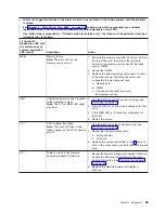
PCI
BRD
The
PCI-X
board
has
failed.
1.
(Trained
service
technician
only)
Reseat
the
PCI-X
board
assembly.
2.
(Trained
service
technician
only)
Replace
the
PCI-X
board
assembly.
CPU
BRD
The
microprocessor
tray
has
failed.
1.
Reseat
the
microprocessor
tray.
2.
(Trained
service
technician
only)
Replace
the
microprocessor
tray.
I/O
BRD
The
I/O
board
has
failed.
1.
Reseat
the
I/O
board.
2.
Replace
the
I/O
board.
Remind
button
You
can
use
the
remind
button
to
put
the
system-error
LED
on
the
operator
information
panel
into
Remind
mode.
When
you
press
the
remind
button,
you
acknowledge
the
error
but
indicate
that
you
will
not
take
immediate
action.
The
system-error
LED
flashes
while
it
is
in
Remind
mode.
The
system-error
LED
stays
in
Remind
mode
until
one
of
the
following
conditions
occurs:
v
All
known
errors
are
corrected.
v
The
server
is
restarted.
v
A
new
error
occurs
(the
LED
is
lit
again).
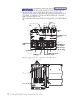
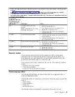
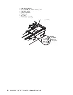
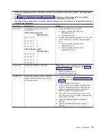
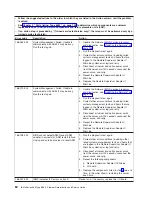
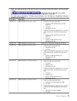
Power-supply
LEDs
The
following
table
describes
the
power-supply
LEDs
and
suggested
actions
to
correct
the
detected
problems.
The
following
minimum
configuration
is
required
for
the
power-supply
dc
good
LED
to
be
lit:
v
Power
supply
v
Power
backplane
v
Power
cord
v
Microprocessor
tray
The
following
minimum
configuration
is
required
for
the
server
to
turn
on:
Chapter
2.
Diagnostics
67
Содержание xSeries 366
Страница 1: ...IBM xSeries 366 Type 8863 Problem Determination and Service Guide...
Страница 2: ......
Страница 3: ...IBM xSeries 366 Type 8863 Problem Determination and Service Guide...
Страница 8: ...vi IBM xSeries 366 Type 8863 Problem Determination and Service Guide...
Страница 28: ...12 IBM xSeries 366 Type 8863 Problem Determination and Service Guide...
Страница 160: ...144 IBM xSeries 366 Type 8863 Problem Determination and Service Guide...
Страница 170: ...154 IBM xSeries 366 Type 8863 Problem Determination and Service Guide...
Страница 181: ...V video connector 6 VRM LED 64 W Web site 1 weight 3 World Wide Web 1 Index 165...
Страница 182: ...166 IBM xSeries 366 Type 8863 Problem Determination and Service Guide...
Страница 183: ......
Страница 184: ...Part Number 31R1508 Printed in USA 1P P N 31R1508...


