


Table
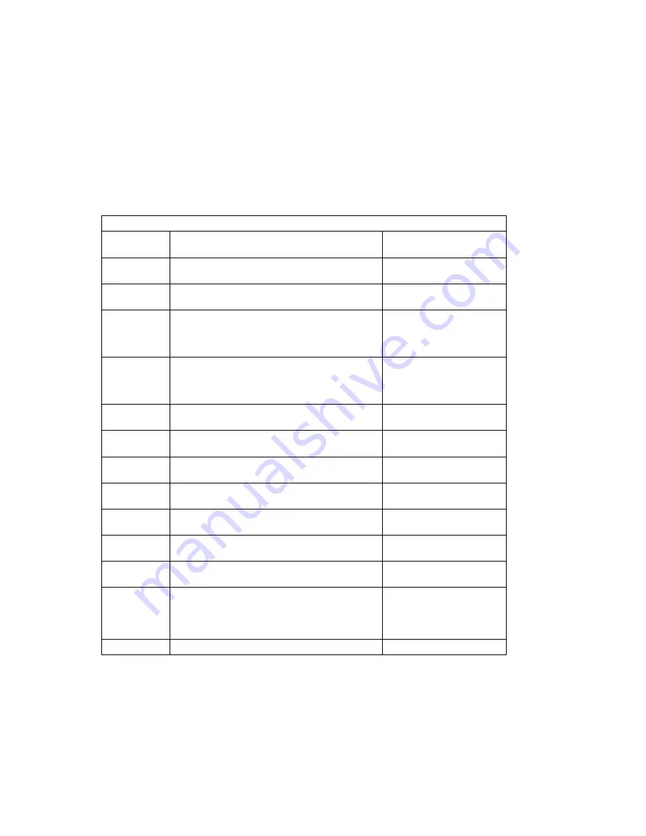
3-3 (Page 9 of 13). POST Error Codes
Error Code
F Code / Description
Action / Possible Failing
FRU
40111092
A low 3.3 voltage reading detected.
1. CPU card
2. Power supply
401110A2
A low 2.5 voltage reading detected.
1. CPU card
2. Power supply
401110B2
A low
+
12 voltage reading detected.
1. Power supply
2. System board; swap
old VPD module to new
system board
401110C2
A low
−
12 voltage reading detected.
1. Power supply
2. System board; swap
old VPD module to new
system board
40200001
An unknown cooling problem detected.
Cooling problem; check
system fans.
40200021
A CPU temperature warning detected.
Over temperature on CPU
card.
40200023
A critical CPU temperature condition detected.
Critical temperature on
CPU card.
40200031
An I/O planar temperature warning detected.
Over temperature on
system board.
40200033
A critical I/O planar temperature condition detected.
Critical temperature on
system board.
40200041
A memory temperature warning detected.
Over temperature on
system board.
40200043
A critical memory temperature condition detected.
Critical temperature on
system board.
40210011
A slow fan detected.
Check:
1. Room operating
temperature
2. System fans
40210014
A stopped fan detected.
Failing fan.
Chapter 3. Error Code to FRU Index
3-11
Содержание RS/6000 7024 E Series
Страница 1: ...RS 6000 7024 E Series IBM Service Guide SA38 0502 03...
Страница 5: ...Power Cables 8 5 Appendix A Firmware Checkpoint Three Digit Codes A 1 Index X 1 Preface v...
Страница 6: ...vi Service Guide...
Страница 18: ...xviii Service Guide...
Страница 20: ...xx Service Guide...
Страница 22: ...Rear View 1 2 Service Guide...
Страница 23: ...Side View with Covers Removed Chapter 1 Reference Information 1 3...
Страница 24: ...Recommended SCSI IDs 1 4 Service Guide...
Страница 82: ...3 18 Service Guide...
Страница 115: ...Post Indicators When the POST is finished the following screen displays Chapter 6 Firmware 6 11...
Страница 122: ...Replacement To replace the cover perform the removal steps in reverse order 7 6 Service Guide...
Страница 134: ...3 Locate the memory module connectors and determine which memory module you want to remove 7 18 Service Guide...
Страница 148: ...7 32 Service Guide...
Страница 149: ...Chapter 8 Parts Information Chapter 8 Parts Information 8 1...
Страница 150: ...8 2 Service Guide...