


Replacement
Attention: This system does not support channel memory, such as memory
expansion adapters.
Note: New memory modules must be installed in the first available vacant
connector, starting at A and progressing to H. The only exception is the
128MB memory module which cannot be installed in connector A due to
space limitations.
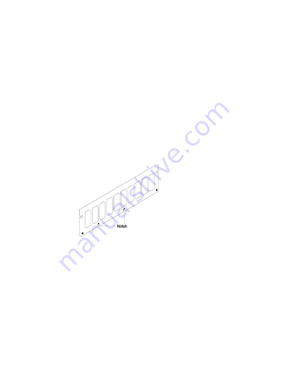
1. The memory modules are keyed so that they can only be inserted one way.
Align the memory module notches with the keys in the memory connectors.
2. Insert the memory module into the next unused memory connector. Push down
on the memory module until the latch tabs lock the memory module into the
connector. (Do not attempt to move the latch tabs yourself. They lock
automatically when you have fully inserted the memory module.)
7-20
Service Guide
Содержание RS/6000 7024 E Series
Страница 1: ...RS 6000 7024 E Series IBM Service Guide SA38 0502 03...
Страница 5: ...Power Cables 8 5 Appendix A Firmware Checkpoint Three Digit Codes A 1 Index X 1 Preface v...
Страница 6: ...vi Service Guide...
Страница 18: ...xviii Service Guide...
Страница 20: ...xx Service Guide...
Страница 22: ...Rear View 1 2 Service Guide...
Страница 23: ...Side View with Covers Removed Chapter 1 Reference Information 1 3...
Страница 24: ...Recommended SCSI IDs 1 4 Service Guide...
Страница 82: ...3 18 Service Guide...
Страница 115: ...Post Indicators When the POST is finished the following screen displays Chapter 6 Firmware 6 11...
Страница 122: ...Replacement To replace the cover perform the removal steps in reverse order 7 6 Service Guide...
Страница 134: ...3 Locate the memory module connectors and determine which memory module you want to remove 7 18 Service Guide...
Страница 148: ...7 32 Service Guide...
Страница 149: ...Chapter 8 Parts Information Chapter 8 Parts Information 8 1...
Страница 150: ...8 2 Service Guide...