


Chapter 2.
Maintenance Analysis Procedures (MAPs)
Entry Map
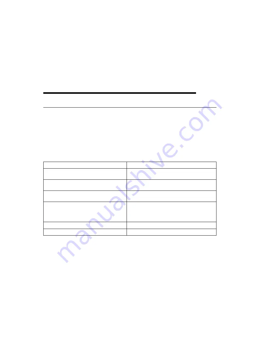
Use the following table to determine your starting point.
Note: When possible, run Online Diagnostics in Service Mode. Online Diagnostics
perform additional functions, compared to Standalone Diagnostics. This will
ensure that the error state of the system is captured in NVRAM for your use
in fixing the problem. The AIX error log and SMIT are only available when
running online diagnostics.
Symptom
Starting Point
You have a problem that does not prevent the
system from booting.
Go to the Fast Path MAP in the
IBM RS/6000
Diagnostic Information for Multiple Bus Systems.
You do not have a symptom.
Go to MAP 0020 in the
IBM RS/6000 Diagnostic
Information for Multiple Bus Systems
You have an SRN.
Go to the Fast Path MAP in the
IBM RS/6000
Diagnostic Information for Multiple Bus Systems.
The system stops and a 3-digit number is
displayed in the operator panel display.
Record SRN 101-xxx, where xxx is the 3-digit
number displayed in the operator panel display,
then go to the Fast Path MAP in the
IBM RS/6000
Diagnostic Information for Multiple Bus Systems.
You have an 8-digit error code.
Go to “Quick Entry MAP” on page 2-2.
The system will not boot.
Go to “Quick Entry MAP” on page 2-2.
Chapter 2. Maintenance Analysis Procedures
2-1
Содержание RS/6000 7024 E Series
Страница 1: ...RS 6000 7024 E Series IBM Service Guide SA38 0502 03...
Страница 5: ...Power Cables 8 5 Appendix A Firmware Checkpoint Three Digit Codes A 1 Index X 1 Preface v...
Страница 6: ...vi Service Guide...
Страница 18: ...xviii Service Guide...
Страница 20: ...xx Service Guide...
Страница 22: ...Rear View 1 2 Service Guide...
Страница 23: ...Side View with Covers Removed Chapter 1 Reference Information 1 3...
Страница 24: ...Recommended SCSI IDs 1 4 Service Guide...
Страница 82: ...3 18 Service Guide...
Страница 115: ...Post Indicators When the POST is finished the following screen displays Chapter 6 Firmware 6 11...
Страница 122: ...Replacement To replace the cover perform the removal steps in reverse order 7 6 Service Guide...
Страница 134: ...3 Locate the memory module connectors and determine which memory module you want to remove 7 18 Service Guide...
Страница 148: ...7 32 Service Guide...
Страница 149: ...Chapter 8 Parts Information Chapter 8 Parts Information 8 1...
Страница 150: ...8 2 Service Guide...