


Table
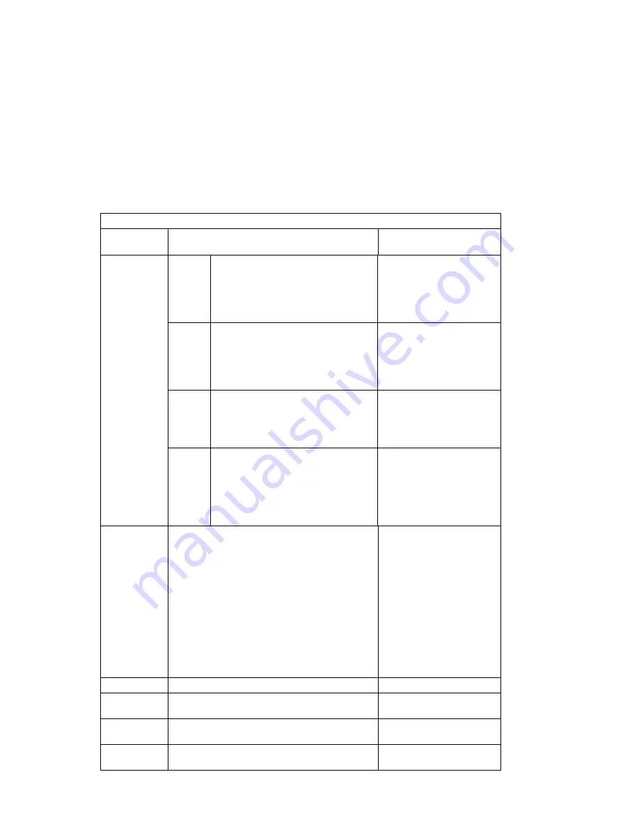
3-3 (Page 1 of 13). POST Error Codes
Error Code
F Code / Description
Action / Possible Failing
FRU
00016000
(continued)
F52
Environmental condition
40210011/40210014, slow/locked fan.
EPOW register could not be cleared.
1. Room operating
temperature
2. System fans
3. System board; swap old
VPD module to new
system board
F53
Environmental condition
40210011/40210014, slow/locked fan.
EPOW register successfully cleared.
1. Fan(s)
2. System board; swap old
VPD module to new
system board
3. Service processor if
present
F55
Unsupported EPOW
1. System board; swap old
VPD module to new
system board
2. Service processor if
present
F56
Environmental condition
40111032/40111092/40111042/401110A2,
3.3V/2.5V high/low. EPOW register
could not be cleared.
1. CPU card
2. Power supply
3. System board; swap old
VPD module to new
system board
4. Service processor if
present
00016010
System VPD access failure
1. System board; swap
old VPD module to new
system board
2. If problem persists,
swap new VPD module
onto new system board;
also see step 3)
3. If customer has
protected licensed
software installed then
advise customer to
contact all protected
software suppliers for a
licence update.
00017001
CMOS error was detected due to battery drainage.
Replace your battery
00017002
Error was detected in CMOS, CMOS data is gone!
CMOS not yet initialized if battery just replaced.
Replace battery if you
haven't done so.
00017003
Power interruption occurred during last Boot
Sequence update.
Update the Boot Sequence
again.
00017006
Tamper Evident is detected or new battery was just
being installed.
Security violation possible.
Chapter 3. Error Code to FRU Index
3-3
Содержание RS/6000 7024 E Series
Страница 1: ...RS 6000 7024 E Series IBM Service Guide SA38 0502 03...
Страница 5: ...Power Cables 8 5 Appendix A Firmware Checkpoint Three Digit Codes A 1 Index X 1 Preface v...
Страница 6: ...vi Service Guide...
Страница 18: ...xviii Service Guide...
Страница 20: ...xx Service Guide...
Страница 22: ...Rear View 1 2 Service Guide...
Страница 23: ...Side View with Covers Removed Chapter 1 Reference Information 1 3...
Страница 24: ...Recommended SCSI IDs 1 4 Service Guide...
Страница 82: ...3 18 Service Guide...
Страница 115: ...Post Indicators When the POST is finished the following screen displays Chapter 6 Firmware 6 11...
Страница 122: ...Replacement To replace the cover perform the removal steps in reverse order 7 6 Service Guide...
Страница 134: ...3 Locate the memory module connectors and determine which memory module you want to remove 7 18 Service Guide...
Страница 148: ...7 32 Service Guide...
Страница 149: ...Chapter 8 Parts Information Chapter 8 Parts Information 8 1...
Страница 150: ...8 2 Service Guide...