background image

Installing a Drive in the Removable Drive Cage

Before you begin

Ÿ

Read “Working with Drives in Bays 1, 2, 3, or 4” on page 47.

Ÿ

Read the documentation that comes with the drive.

Ÿ

Remove the drive cage. See “Removing the Drive Cage” on page 48.

1

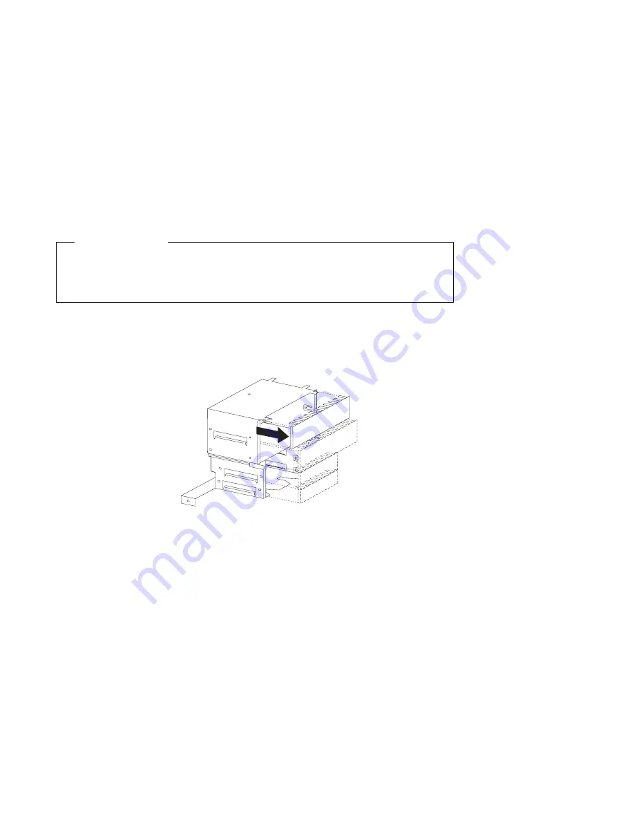
With the front of the drive cage facing you, pull out the tabs on the sides of
the metal shield until it flexes. Lift off one side, then the other.

2

Touch the static-protective package containing the new drive to any unpainted
metal surface and then remove the drive from it.

50

Installing Options in Your Personal Computer 


Содержание PC 300GL Type 6591

Страница 1: ...Personal Computer Installing Options in Your Personal Computer PC 300GL Type 6591...

Страница 2: ......

Страница 3: ...Personal Computer Installing Options in Your Personal Computer PC 300GL Type 6591 IBM...

Страница 4: ...ly made to the information herein these changes will be incorporated in new editions of the publication IBM may make improvements and or changes in the product s and or the program s described in this...

Страница 5: ...rnal View 9 Input Output Connectors 10 Chapter 3 Working with Options on the System Board 11 Accessing the System Board 12 Identifying Parts on the System Board 12 Working with System Memory 13 Memory...

Страница 6: ...5 and 6 64 Chapter 6 Working with Security Options 67 Installing a U Bolt 68 Erasing Lost or Forgotten Passwords 70 Chapter 7 Completing the Installation 74 Replacing the Side Cover and Connecting the...

Страница 7: ...es to devices In the U K by law the power cord must be disconnected after the telephone line cable 2 In the U K by law the telephone cable must be connected after the power cord 1 2 1 Electrical curre...

Страница 8: ...al Commission IEC 825 and CENELEC EN 60 825 for Class 1 laser products When a CD ROM drive is installed note the following CAUTION Use of controls or adjustments or performance of procedures other tha...

Страница 9: ...le Dispose of the battery as required by local ordinances or regulations ATTENTION Danger d explosion en cas de remplacement incorrect de la batterie Remplacer uniquement par une batterie IBM de type...

Страница 10: ...des instructions for installing removing and replacing most options Also this book contains information to help you decide which options to add to your computer Note The illustrations in this publicat...

Страница 11: ...ing and removing adapters Chapter 5 Working with Internal Drives provides instructions for installing and removing drives Chapter 6 Working with Security Options describes features such as the securit...

Страница 12: ...f your computer About Your Software This publication provided only with computers that have IBM preinstalled software contains information about the preinstalled software package Your Ready to Configu...

Страница 13: ...n Manual This publication is only available on the World Wide Web at http www us pc ibm com support desktop desktop_support html It contains more information about the technical aspects of your comput...

Страница 14: ...xii Installing Options in Your Personal Computer...

Страница 15: ...ion to the options and features that are available for your computer Also important information about required tools electrical safety and static sensitive devices is included Important Before you ins...

Страница 16: ...y started using an optional network adapter that supports Wake on LAN For more information on Wake on LAN see Using Your Personal Computer In some models an audio adapter is preinstalled in one of the...

Страница 17: ...al information and download device drivers and updates Some of these pages are http www ibm com Main IBM home page http www pc ibm com IBM Personal Computer home page http www us pc ibm com desktop IB...

Страница 18: ...ernal drives Note Personal computer users in the United Kingdom who have a modem or fax machine attached to their computer must disconnect the telephone line from the computer before unplugging any po...

Страница 19: ...around you Always handle components carefully Handle adapters and memory modules by the edges Never touch any exposed circuitry Prevent others from touching components When you are installing a new o...

Страница 20: ...Warning The presence of 5 V standby power might result in damage to your hardware unless you disconnect the power cord from the electrical outlet before opening the computer 1 Unplug all power cords f...

Страница 21: ...Lock 5 One side of the cover is removable and has a cover release tab at the back edge 6 Pull out on the cover release tab at the rear of the side cover and slide the side cover toward the front of t...

Страница 22: ...l view of your computer as seen from the front For information on removing the cover see Disconnecting Cables and Removing the Side Cover on page 6 Note The following illustration is for reference onl...

Страница 23: ...sk drive light 4 Client LAN light not used 5 Bay 1 CD ROM drive 6 CD ROM eject button 7 CD ROM emergency eject 8 Bay 2 9 Bay 3 1 Bay 4 3 5 diskette drive S o c k e t 7 S o c k e t 7 Your computer come...

Страница 24: ...ation on the ports and their specific technologies see Understanding Your Personal Computer At the rear of your computer is a panel that provides access to the I O connectors Adapters installed in exp...

Страница 25: ...ormation Run ConfigSafe or a similar application to take a snapshot of your computer configuration before installing an adapter This allows you to view and compare the changes in the computer configur...

Страница 26: ...plan to install remove or replace hardware in your computer you will need to know the layout of the system board The following illustration shows the layout of the system board in your computer The n...

Страница 27: ...DIMM 0 DIMM 1 The memory modules your computer uses are dual inline memory modules DIMMs The IBM installed DIMMs that come with your computer are nonparity NP or ECC error correcting code SDRAM synchr...

Страница 28: ...on the System Board on page 12 The following table shows possible memory configurations for your computer this table and additional information are also found inside the computer Note Values in the f...

Страница 29: ...cover see Disconnecting Cables and Removing the Side Cover on page 6 Lay the computer on its side Note For information on memory configuration see Table 1 on page 14 1 To locate the memory connectors...

Страница 30: ...ning clips pop up and snugly fit around both ends of the module 6 To install another memory module repeat steps 1 5 7 Go to the device record form in Using Your Personal Computer and record this insta...

Страница 31: ...he computer cover see Disconnecting Cables and Removing the Side Cover on page 6 Lay the computer on its side 1 To locate the memory connectors inside your computer see Identifying Parts on the System...

Страница 32: ...t to do next To work with another option go to the appropriate section To complete the installation go to Chapter 7 Completing the Installation on page 74 18 Installing Options in Your Personal Comput...

Страница 33: ...ocessor and heat sink will be hot if the computer has been running To avoid the possibility of a burn if the computer has been on let the microprocessor and heat sink cool for 10 minutes before contin...

Страница 34: ...r index fingers on the small tabs on the top of the microprocessor Push in toward the microprocessor until the tabs release Tabs 3 Carefully place one hand on the computer frame and with the other han...

Страница 35: ...ted metal surface in the computer and then remove the new microprocessor 6 Press in on the retainer tabs until they click into place 7 Align the new microprocessor with the connector on the system boa...

Страница 36: ...ts or hardware damage might occur See Updating the Computer Configuration on page 77 and Setting the Microprocessor Speed on page 84 Note If a 167 POST error occurs when you start your computer refer...

Страница 37: ...e instructions that come with your adapter to determine if it is Plug and Play For more information see Adapter Configuration on page 26 Important Information Run ConfigSafe or a similar application t...

Страница 38: ...The riser card in your computer has three dedicated ISA slots and three dedicated PCI slots The following illustration shows the expansion slots and connectors on the riser card Fan Modem Wakeup PCI P...

Страница 39: ...on the back side of the riser card When installing optional drives refer to the following illustration for the location of the appropriate connectors LED Panel Primary IDE Secondary IDE Diskette Drive...

Страница 40: ...r remove Plug and Play adapters this information is interpreted by the basic input output system BIOS which supports Plug and Play technology If the required resources are available the BIOS software...

Страница 41: ...ISA Resource this reserves the resources for the legacy adapter and prevents the BIOS from using these resources for the system or other Plug and Play adapters Just as you change system resources whe...

Страница 42: ...hat come with the new adapter Turn off the computer and all other connected devices Disconnect all cables attached to the computer see Disconnecting Cables and Removing the Side Cover on page 6 Remove...

Страница 43: ...ng the Bottom Cover on page 38 Note Some computers might have a single bracket that holds all the slot covers in place Expansion Slot Cover Riser Card 3 Touch the static protective package containing...

Страница 44: ...adapter interferes with the installation use another slot Adapter Card Riser Card 5 If you removed the bottom cover the fan or the system board replace them See Removing and Replacing the Fan on page...

Страница 45: ...connect all cables attached to the computer Remove the computer cover see Disconnecting Cables and Removing the Side Cover on page 6 Lay the computer on its side To remove some adapters you might need...

Страница 46: ...Fan on page 40 Removing and Replacing the System Board on page 33 and Removing and Replacing the Bottom Cover on page 38 5 Go to the device record form in Using Your Personal Computer and delete the n...

Страница 47: ...You might encounter two different styles of rails on the right hand side of the system board Style 1 has no latching mechanism Style 2 has a tab that engages in an opening in the chassis to hold the...

Страница 48: ...sition This releases the system board from the riser card 3 Grasp both rails supporting the system board and carefully slide the system board out and set it aside CAUTION Do not pull on the microproce...

Страница 49: ...asp and turn the latch clockwise to the extended position This releases the system board from the riser card 4 Grasp the rails supporting the system board and carefully slide the system board out and...

Страница 50: ...he end of the right hand rail When the system board is fully seated the alignment mark on the chassis is visible CAUTION Do not push on the microprocessor memory modules memory sockets or other system...

Страница 51: ...nd rail When the system board is fully seated the tab on the right hand rail is engaged in an opening in the chassis CAUTION Do not push on the microprocessor memory modules memory sockets or other sy...

Страница 52: ...e new adapter Turn off the computer and all other connected devices Disconnect all cables attached to the computer Remove the computer cover see Disconnecting Cables and Removing the Side Cover on pag...

Страница 53: ...ngs in the frame 3 Fit the tabs into the openings and pivot the bottom cover until it is closed 4 Align the holes and insert the two bottom screws What to do next To work with another option go to the...

Страница 54: ...f the computer and all other connected devices Disconnect all cables attached to the computer Remove the computer cover see Disconnecting Cables and Removing the Side Cover on page 6 Lay the computer...

Страница 55: ...into position and push down on the tab to latch 3 Connect the fan cable to the riser card See the label inside the computer for the location of the fan connector 4 Replace the bottom cover see Removi...

Страница 56: ...ving internal drives When you are installing an internal drive it is important to note which drive types and sizes you can install in each bay Also it is important to correctly connect the internal dr...

Страница 57: ...r computer The bays are referred to as bay 1 bay 2 and so on Drive bays 1 through 4 at the front of your computer are contained in one drive cage and drive bays 5 and 6 at the back of your computer ar...

Страница 58: ...rive 25 4 1 0 25 4 1 0 4 3 5 inch diskette drive 25 4 1 0 5 Hard disk drive 25 4 1 0 25 4 1 0 6 Hard disk drive 25 4 1 0 25 4 1 0 Notes You cannot install drives that are greater than 41 3 mm 1 6 in h...

Страница 59: ...er signal cable attaches to the installed hard disk drive and to the primary IDE connector on the back of the riser card The narrower signal cable attaches to the diskette drive and to the diskette dr...

Страница 60: ...wise some of the IDE devices might not be recognized by the system The master or slave designation is determined by switch or jumper settings on each IDE device To optimize performance when installing...

Страница 61: ...e In this type the drive cage is permanently mounted to the chassis and cannot be removed To determine which type of chassis you have look for the support bracket and screw that secures the front driv...

Страница 62: ...nd all other connected devices Disconnect all cables attached to the computer Remove the computer cover see Disconnecting Cables and Removing the Side Cover on page 6 Lay the computer on its side If y...

Страница 63: ...crew from the drive support bracket that holds the drive cage for bays 1 through 4 in place Then pull the drive cage towards the power supply until it stops and lift it out of the computer S o c k e t...

Страница 64: ...the drive cage See Removing the Drive Cage on page 48 1 With the front of the drive cage facing you pull out the tabs on the sides of the metal shield until it flexes Lift off one side then the other...

Страница 65: ...1 4 Insert the drive cage and slide it to the right until it docks against the front of the computer be sure the screwholes in the drive cage and support bracket are aligned 5 Insert and tighten the...

Страница 66: ...card 7 If you have installed a drive with removable media you must remove the bay panel If you have installed a drive with nonremovable media you must install a bay panel if not already installed To r...

Страница 67: ...opriate bay panel in the computer cover b Use the tip of a screwdriver if necessary to flex the plastic tabs holding the bay panel in the cover c Remove the bay panel d Continue to step 10 on page 54...

Страница 68: ...ng in the front of the computer b Gently press the left edge closed until it snaps c Go to Installing a Drive in the Removable Drive Cage on page 50 10 Go to the device record form in Using Your Perso...

Страница 69: ...Drives in Bays 1 2 3 or 4 on page 47 Remove the drive cage See Removing the Drive Cage on page 48 1 Disconnect the cables from the drive you want to remove 2 Remove the screws holding the drive in pl...

Страница 70: ...drive go to Installing a Drive in the Removable Drive Cage on page 50 5 If you are not installing another drive a Insert the metal shield into the front drive cage b Install the bay panel into the fro...

Страница 71: ...he drive cage at the side then the screw on top near the handle S o c k e t 7 S o c k e t 7 S o c k e t 7 S o c k e t 7 e Attach the cables to the remaining drives Refer to Power and Signal Cables on...

Страница 72: ...permanently mounted front drive cage 1 Remove the bay panel for the drive bay where you are installing the drive a Locate the appropriate bay panel b Use the tip of a screwdriver if necessary to flex...

Страница 73: ...opening and secure it with the screws provided 4 Attach the cables Refer to Power and Signal Cables on page 45 for an illustration showing the locations of the connectors on the riser card Chapter 5 W...

Страница 74: ...the installed drive has nonremovable media replace the bay panel 6 Go to the device record form in Using Your Personal Computer and record the installation 60 Installing Options in Your Personal Comp...

Страница 75: ...permanently mounted front drive cage 1 If the drive being removed has nonremovable media remove the bay panel a Locate the appropriate drive bay b Use the tip of a screwdriver to flex the plastic tab...

Страница 76: ...2 Disconnect the cables from the drive you want to remove 3 Remove the visible screws holding the drive and slide it out the front of the computer 62 Installing Options in Your Personal Computer...

Страница 77: ...4 If you are not installing another drive replace the bay panel 5 Go to the device record form in Using Your Personal Computer and record the removal Chapter 5 Working with Internal Drives 63...

Страница 78: ...ys 5 and 6 must have nonremovable media Your computer comes with a hard disk drive in bay 6 To install or remove drives in these bays you must remove the rear drive cage To install or remove drives in...

Страница 79: ...are removing a drive remove the screws holding the drive in the cage and slide the drive out of the cage If you are installing a drive slide the drive into the bay and secure it with the screws Note T...

Страница 80: ...screw or snap you removed in step 1 6 Connect the cables to the drive 7 Go to the device record form in Using Your Personal Computer and write the adapter name next to the slot into which you install...

Страница 81: ...mputer To erase lost or forgotten passwords you can move the CMOS clear password jumper on the system board Note Use the Configuration Setup Utility program to set change or delete passwords For more...

Страница 82: ...ck or padlock An adjustable wrench Read Electrical Safety on page 4 and Handling Static Sensitive Devices on page 5 Turn off the computer and all connected devices Disconnect all external cables and p...

Страница 83: ...through the U bolt and around an object that is not a part of or permanently secured to the building structure or foundation and from which it cannot be removed then fasten the cable ends together wi...

Страница 84: ...nformation Plug and Play configuration information Port assignments I O addresses and interrupts Other selectable features Within the security features are the settings for the power on and administra...

Страница 85: ...nect the power cord from the rear of the chassis Leave the other cables connected Remove the computer cover see Disconnecting Cables and Removing the Side Cover on page 6 Lay the computer on its side...

Страница 86: ...or crush the jumper 1 2 3 1 2 3 1 2 3 CAUTION Do not touch any of the internal components of the computer 2 Reconnect the power cord and turn the computer back on CMOS memory is now cleared and the p...

Страница 87: ...ff 5 Disconnect the power cord from the rear of the chassis 6 Move the jumper back to its normal position pins 1 and 2 1 2 3 1 2 3 1 2 3 What to do next After reassembling the computer go to Chapter 7...

Страница 88: ...wer cords and telephone lines Also depending on the option installed you might need to update information in the Configuration Setup Utility program The following list is a quick reference to the comp...

Страница 89: ...ear any cables that might impede the replacement of the cover 3 Make sure the cover lock if present is in the unlocked position Note It is easier to install the cover if the computer is laying on it s...

Страница 90: ...e attached to the computer reconnect the telephone line to the wall outlet and the serial port Plug the power cords into properly grounded electrical outlets 8 Update the computer configuration See Up...

Страница 91: ...y by the computer but you must save the changes or manually by you When the computer automatically configures an option it uses system programs If the system programs do not update the settings you ca...

Страница 92: ...ter the following screen might appear Note Depending on the configuration changes that occurred the error message you see might be different from the one shown here If the preceding screen appears sel...

Страница 93: ...et both an administrator and a power on password you can type either of the passwords at the password prompt However if you type your power on password you can view limited information in the Configur...

Страница 94: ...nfiguration change occurred in that category The 5 might also appear in subsequent menus If an asterisk is beside a menu item a resource conflict is detected When you complete your changes or finish v...

Страница 95: ...Setup Utility program see Starting the Configuration Setup Utility Program on page 78 2 Select ISA Legacy Resources from the Configuration Setup Utility menu 3 As needed select Memory Resources I O Po...

Страница 96: ...Utility program see Starting the Configuration Setup Utility Program on page 78 2 Select Start Options from the Configuration Setup Utility menu 3 Select First Startup Device 4 Use the arrow keys to...

Страница 97: ...1 Start the Configuration Setup Utility program see Starting the Configuration Setup Utility Program on page 78 2 Select System Security from the Configuration Setup Utility menu 3 Select Administrat...

Страница 98: ...hardware damage might occur For more information about the microprocessor speed see Using Your Personal Computer To set the microprocessor speed 1 Start the Configuration Setup Utility program see Sta...

Страница 99: ...trical Safety on page 4 and Handling Static Sensitive Devices on page 5 Read the instructions that come with the replacement battery Turn off the computer and all connected devices Disconnect all exte...

Страница 100: ...with another option go to the appropriate section To complete the replacement go to Chapter 7 Completing the Installation on page 74 Use the Configuration Setup Utility program to set the date and ti...

Страница 101: ...rupt Controller 31 Serial Port 2 or Infrared 41 Serial Port 51 Audio Adapter if installed 6 Diskette 71 Parallel Port 8 Real Time Clock 9 ACPI 10 Available 11 Available 121 Mouse 13 Coprocessor 14 IDE...

Страница 102: ...n and verification of operation in conjunction with other products except those expressly designated by IBM are the responsibility of the user IBM may have patents or pending patent applications cover...

Страница 103: ...les continued types for internal drives 45 cage installing drives 50 permanently mounted 58 rear 64 removable 48 removing drives 55 61 64 cage rear 64 CD ROM drive 8 9 43 44 clearing CMOS 70 completin...

Страница 104: ...4 F fan removal 40 replacement 40 fixed disk drive 44 front drive cage 50 55 58 61 H handling batteries 85 static sensitive devices 5 hard disk drive 43 44 hardware removing 12 home page IBM Personal...

Страница 105: ...ee system memory memory modules configuration 14 installing 15 location on system board 12 removing 17 types 13 microprocessor location on system board 12 replacing 19 setting the speed 84 upgrade 19...

Страница 106: ...s 45 riser card diagram 24 expansion slots 24 ISA slots 24 location on system board 12 PCI slots 24 S safety battery handling 85 electrical 4 information v procedures and guidelines 1 safety notice ba...

Страница 107: ...lt installing 68 unknown power on password removing 70 updating computer configuration 77 upgrading memory modules 13 microprocessor 19 USB port 10 utility program setup 77 W Wake on LAN hardware for...

Страница 108: ...IBM Part Number 05L1940 Printed in U S A January 1998 5L194...

Отзывы: