


4.
Remove
the
hard
disk
drive.
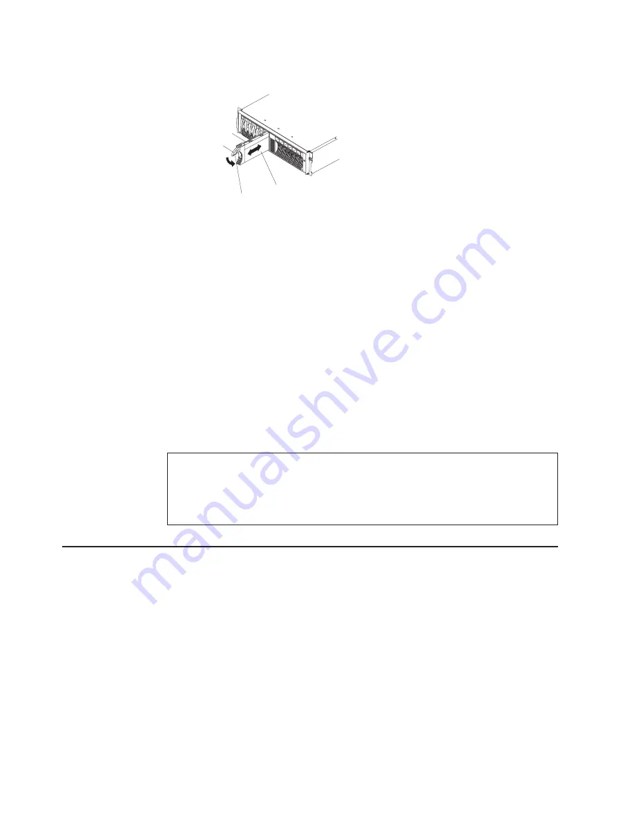
Drive tray
Tray handle
Latch
Hard disk drive
a.
Press
the
latch
on
the
bottom
of
the
tray
handle
to
release
it.
b.
Pull
out
the
tray
handle
to
the
open
position.
c.
Lift
the
drive
partially
out
of
the
bay
and
wait
at
least
20
seconds
before
fully
removing
the
drive
from
the
expansion
unit.
This
enables
the
drive
to
spin
down
and
avoids
possible
damage
to
the
drive.
d.
Verify
that
there
is
proper
identification
(such
as
a
label)
on
the
hard
disk
drive;
then,
gently
slide
it
completely
out
of
the
expansion
unit.
5.
Install
the
new
hard
disk
drive.
a.
Gently
push
the
drive
into
the
empty
bay
until
the
tray
handle
touches
the
expansion
unit
tray.
b.
Push
down
the
tray
handle
into
the
closed
(latched)
position.
6.
Check
the
hard
disk
drive
LEDs.
a.
When
a
drive
is
ready
for
use,
the
green
activity
LED
and
the
amber
status
LED
are
off.
b.
If
the
amber
status
LED
is
lit
and
not
flashing,
remove
the
drive
from
the
unit
and
wait
10
seconds;
then,
reinstall
the
drive.
If
the
amber
LED
is
flashing,
the
drive
is
rebuilding.
ServeRAID
information
In
some
cases,
the
ServeRAID
controller
will
automatically
reset
the
drive
to
the
Hot
Spare
or
Rebuild
state.
If
the
drive
state
change
does
not
occur
automatically
(amber
LED
stays
lit),
refer
to
your
ServeRAID
documentation
for
information
about
manually
changing
the
state
of
the
drive
from
the
current
state
to
another
state,
such
as
Hot
Spare
or
Ready.
The
amber
LED
should
turn
off
within
10
seconds
after
the
drive-state
change.
Replacing
a
bridge
card
Attention:
Before
replacing
the
bridge
card,
you
must
turn
off
the
expansion
unit.
See
“Turning
off
the
expansion
unit”
on
page
11
for
detailed
instructions.
Complete
the
following
steps
to
replace
the
bridge
card:
1.
Read
“Installation
guidelines”
on
page
23
and
the
safety
information
beginning
on
page
37.
2.
Turn
off
the
expansion
unit.
See
“Turning
off
the
expansion
unit”
on
page
11.
3.
For
easier
removal
and
installation
of
the
bridge
card,
remove
the
hard
disk
drive
or
filler
panel
from
drive
bays
7
and
8
(the
drive
bays
immediately
left
and
right
of
the
bridge
card
bay).
You
do
not
need
to
remove
all
of
the
hard
disk
drives
and
filler
panels.
For
instructions
for
removing
filler
panels
or
hard
disk
drives,
see
“Replacing
a
hot-swap
hard
disk
drive”
on
page
25.
26
IBM
EXP400
Storage
Expansion
Unit
Type
1733:
Hardware
Maintenance
Manual
and
Troubleshooting
Guide
Содержание EXP400 Type 1733
Страница 2: ......
Страница 22: ...14 IBM EXP400 Storage Expansion Unit Type 1733 Hardware Maintenance Manual and Troubleshooting Guide...
Страница 38: ...30 IBM EXP400 Storage Expansion Unit Type 1733 Hardware Maintenance Manual and Troubleshooting Guide...
Страница 58: ...50 IBM EXP400 Storage Expansion Unit Type 1733 Hardware Maintenance Manual and Troubleshooting Guide...
Страница 59: ...Laser Klass 1 Appendix B Related service information 51...
Страница 60: ...52 IBM EXP400 Storage Expansion Unit Type 1733 Hardware Maintenance Manual and Troubleshooting Guide...
Страница 61: ...Appendix B Related service information 53...
Страница 62: ...54 IBM EXP400 Storage Expansion Unit Type 1733 Hardware Maintenance Manual and Troubleshooting Guide...
Страница 63: ...Luokan 1 Laserlaite Important Appendix B Related service information 55...
Страница 77: ...Appendix B Related service information 69...
Страница 78: ...70 IBM EXP400 Storage Expansion Unit Type 1733 Hardware Maintenance Manual and Troubleshooting Guide...
Страница 79: ...Appendix B Related service information 71...
Страница 80: ...72 IBM EXP400 Storage Expansion Unit Type 1733 Hardware Maintenance Manual and Troubleshooting Guide...
Страница 86: ...78 IBM EXP400 Storage Expansion Unit Type 1733 Hardware Maintenance Manual and Troubleshooting Guide...
Страница 94: ...86 IBM EXP400 Storage Expansion Unit Type 1733 Hardware Maintenance Manual and Troubleshooting Guide...
Страница 97: ......
Страница 98: ...Part Number 90P3548 1P P N 90P3548...


