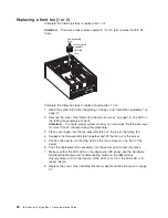


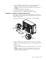
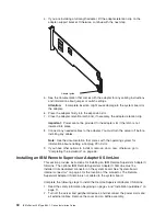
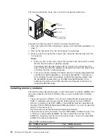
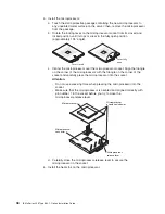
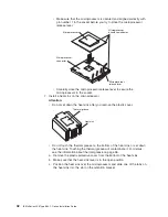
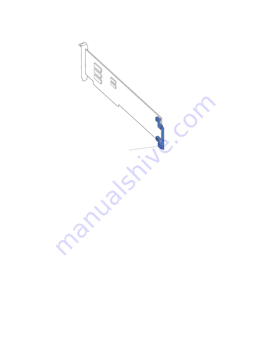
4.
If
you
are
installing
a
full-length
adapter,
lift
the
adapter-retention
clip
on
the
adapter-support
bracket.
Otherwise,
continue
with
the
next
step.
Adapter guide
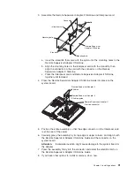
5.
See
the
documentation
that
comes
with
the
adapter
for
any
cabling
instructions
and
information
about
jumper
or
switch
settings.
Attention:
Incomplete
insertion
might
cause
damage
to
the
system
board
or
the
adapter.
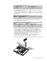
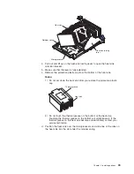
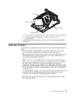
6.
Press
the
adapter
firmly
into
the
expansion
slot.
7.
Close
the
adapter-retention
latch
and,
if
necessary,
the
adapter-retention
clip.
Important:
Power
cannot
be
provided
to
the
adapter
slot
if
the
latch
is
not
lowered
into
place.
8.
Connect
any
needed
cables
to
the
adapter.
You
must
turn
the
server
off
before
installing
any
cables.
Note:
See
the
documentation
that
comes
with
the
operating
system
for
information
about
enabling
a
hot-plug
PCI-X
slot.
9.
If
you
have
other
options
to
install
or
remove,
do
so
now;
otherwise,
go
to
“Completing
the
installation”
on
page
46.
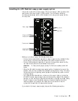
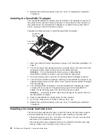
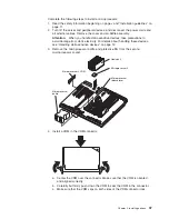
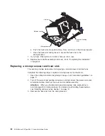
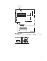
Installing
an
IBM
Remote
Supervisor
Adapter
II
SlimLine
This
section
provides
instructions
for
installing
an
IBM
Remote
Supervisor
Adapter
II
SlimLine.
The
optional
IBM
Remote
Supervisor
Adapter
II
SlimLine
must
be
installed
in
its
dedicated
connector
on
the
system
board.
See
“System-board
internal
connectors”
on
page
4
for
the
location
of
the
connector.
The
Remote
Supervisor
Adapter
II
SlimLine
is
not
cabled
to
the
system
board.
Complete
the
following
steps
to
install
the
Remote
Supervisor
Adapter
II
SlimLine:
1.
Read
the
safety
information
beginning
on
page
v
and
“Installation
guidelines”
on
page
11.
2.
Turn
off
the
server
and
peripheral
devices,
and
disconnect
the
power
cords
and
all
external
cables.
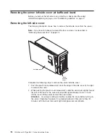
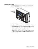
Remove
the
cover
and
air
baffle
assembly.
30
IBM
xSeries
236
Type
8841:
Option
Installation
Guide
Содержание 8841 - eServer xSeries 236
Страница 1: ...IBM xSeries 236 Type 8841 Option Installation Guide ERserver...
Страница 2: ......
Страница 3: ...IBM xSeries 236 Type 8841 Option Installation Guide ERserver...
Страница 22: ...10 IBM xSeries 236 Type 8841 Option Installation Guide...
Страница 64: ...52 IBM xSeries 236 Type 8841 Option Installation Guide...
Страница 73: ......
Страница 74: ...Part Number 31R1191 Printed in USA 1P P N 31R1191...


