

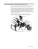


Chapter
2.
Installing
options
This
chapter
provides
detailed
instructions
for
installing
hardware
options
in
the
server.
Installation
guidelines
Before
you
begin
installing
options
in
the
server,
read
the
following
information:
v
For
a
list
of
supported
options
for
the
server,
go
to
http://www.ibm.com/servers/eserver/severproven/compat/us/.
v
Read
the
safety
information
beginning
on
page
v
and
the
guidelines
in
“Handling
static-sensitive
devices”
on
page
12.
This
information
will
help
you
work
safely
with
the
server
and
options.
v
Make
sure
that
you
have
an
adequate
number
of
properly
grounded
electrical
outlets
for
the
server,
monitor,
and
other
devices.
v
Back
up
all
important
data
before
you
make
changes
to
disk
drives.
v
Have
a
small
flat-blade
screwdriver
available.
v
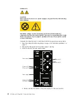
You
do
not
have
to
turn
off
the
server
to
install
or
replace
hot-swap
power
supplies,
hot-swap
fans,
or
hot-plug
Universal
Serial
Bus
(USB)
devices.
v
Blue
on
a
component
indicates
touch
points,
where
you
can
grip
the
component
to
remove
it
from
or
install
it
in
the
server,
open
or
close
a
latch,
and
so
on.
v
Orange
on
a
component
or
an
orange
label
on
or
near
a
component
indicates
that
the
component
can
be
hot-swapped,
which
means
that
if
the
server
and
operating
system
support
hot-swap
capability,
you
can
remove
or
install
the
component
while
the
server
is
running.
(Orange
can
also
indicate
touch
points
on
hot-swap
components.)
See
the
instructions
for
removing
or
installing
a
specific
hot-swap
component
for
any
additional
procedures
that
you
might
have
to
perform
before
you
remove
or
install
the
component.
v
When
you
need
to
access
the
inside
of
the
server,
you
might
find
it
easier
to
lay
the
server
on
its
side.
System
reliability
guidelines
To
help
ensure
proper
cooling
and
system
reliability,
make
sure
that:
v
Each
of
the
drive
bays
has
a
drive
or
a
filler
panel
and
electromagnetic
compatibility
(EMC)
shield
installed
in
it.
v
There
is
adequate
space
around
the
server
to
allow
the
server
cooling
system
to
work
properly.
Leave
approximately
50
mm
(2.0
in.)
of
open
space
around
the
front
and
rear
of
the
server.
Do
not
place
objects
in
front
of
the
fans.
For
proper
cooling
and
airflow,
replace
the
left-side
cover
before
turning
on
the
server.
Operating
the
server
for
extended
periods
of
time
(more
than
30
minutes)
with
the
left-side
cover
removed
might
damage
server
components.
v
You
have
followed
the
cabling
instructions
that
come
with
optional
adapters.
v
You
have
replaced
a
failed
fan
within
48
hours.
v
You
have
replaced
a
hot-swap
drive
within
2
minutes
of
removal.
v
You
do
not
remove
the
air
baffle
while
the
server
is
running.
Operating
the
server
without
the
air
baffle
might
cause
the
microprocessor
to
overheat.
v
Microprocessor
socket
2
always
contains
either
a
microprocessor
baffle
or
a
microprocessor
and
heat
sink.
©
Copyright
IBM
Corp.
2005
11
Содержание 8841 - eServer xSeries 236
Страница 1: ...IBM xSeries 236 Type 8841 Option Installation Guide ERserver...
Страница 2: ......
Страница 3: ...IBM xSeries 236 Type 8841 Option Installation Guide ERserver...
Страница 22: ...10 IBM xSeries 236 Type 8841 Option Installation Guide...
Страница 64: ...52 IBM xSeries 236 Type 8841 Option Installation Guide...
Страница 73: ......
Страница 74: ...Part Number 31R1191 Printed in USA 1P P N 31R1191...


