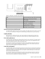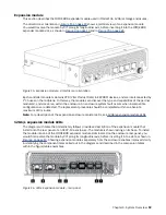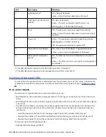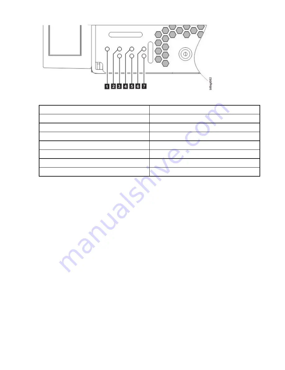
Figure 12. Front panel – lower left corner (partial view)
LED
Front panel functions (lower left cornerof panel)
1
System Power On/Standby LED (Green)
2
ID LED (Blue)
3
Drive Activity LED (blinking Green)
4
Fault LED – Top lid (Amber)
5
Firmware Fault LED (Amber)
6
Module Fault LED – rear (Amber)
7
Fault LED– Left rear lid (Amber)
System Power On/Standby LED (green)
The LED illuminates green when system power is available. If the LED is off, either the system is powered
off, or there is a power failure in the system. Troubleshooting to identify the root cause is necessary.
Identify LED (blue)
When activated, the Identity LED is blue, and is used to identify the storage system amongst many
installed in the rack. This LED is normally off, and illuminates only during the identification process.
Drive Activity LED (Green)
The LED illuminates blinking-green to indicate disk drive activity. If the enclosure is in operation and the
LED is not blinking, there is a possibility of a disk drive fault. This LED can be used together with other
Fault LEDs to determine whether a drive fault condition exists.
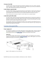
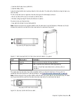
Pull the chassis forward from its installed position within the rack. Remove the top lid and look for an
amber LED on any of the disk drive modules or HS expander modules on the side plane. Replace the
faulty module per the applicable CRU replacement procedure.
Fault LED–Top lid(amber)
The LED illuminates amber when experiencing a system hardware fault with a component accessible via
the enclosure top panel. Amber display indicates that the top lid should be removed to locate the faulty
component within the drive channel. This LED is normally off, and illuminates only when a fault occurs
with a component beneath the top lid.
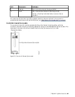
Pull the chassis forward from its installed position within the rack. Remove the top lid and look for an
amber LED on any of the disk drive modules or HS expander modules on the side plane. Replace the
faulty module per the applicable CRU replacement procedure.
Chapter 3. System Overview 15
Содержание 106
Страница 1: ...IBM ESS expansion Version 5 3 5 Hardware Installation and Maintenance Guide Model 106 IBM SC27921101...
Страница 6: ...Russia Electromagnetic Interference Class A Statement 100 Homologation statement 100 vi...
Страница 12: ...xii...
Страница 18: ...xviii IBM ESS expansion Hardware Installation and Maintenance Guide Model 106...
Страница 20: ...2 IBM ESS expansion Hardware Installation and Maintenance Guide Model 106...
Страница 44: ...26 IBM ESS expansion Hardware Installation and Maintenance Guide Model 106...
Страница 53: ...Figure 28 CMA attachment aligned with outer slide Figure 29 Panhead screws Chapter 4 Installation 35...
Страница 84: ...66 IBM ESS expansion Hardware Installation and Maintenance Guide Model 106...
Страница 100: ...82 IBM ESS expansion Hardware Installation and Maintenance Guide Model 106...
Страница 108: ...90 IBM ESS expansion Hardware Installation and Maintenance Guide Model 106...
Страница 119: ......
Страница 120: ...IBM SC27921101...


