background image

Note:

The self-adhesive dots are used to aid in identifying locations on the rack. If you do not have

the dots, use some other form of marking tool to aid you in identifying hole locations (for example,
tape, or a marker). You will need to identify the marked hole from both the front and back of the
rack.

3.

Place another self-adhesive dot next to the middle hole of the bottom EIA unit on the left side of the
rack.

4.

Go to the back of the rack. On the right side, find the EIA unit that corresponds to the bottom EIA
unit marked on the front of the rack.

Note:

The following figure is an example of how the EIA units appear, you might have a different

configuration or placement.
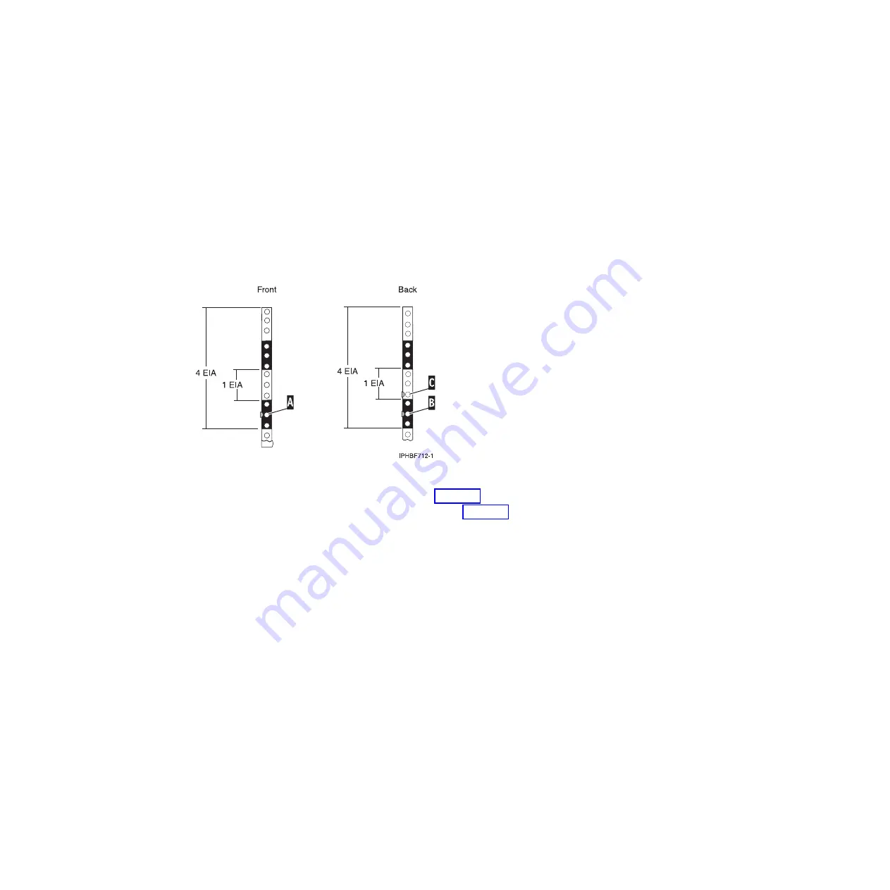
5.

Place a self-adhesive dot at the middle hole of the bottom EIA unit,

(B)

in Figure 68.

6.

Place a self-adhesive dot at the bottom hole of the next (higher) EIA unit,

(C)

in Figure 68.

7.

Mark the corresponding holes on the left side of the rack.

Attaching the mounting hardware to the rack

You might need to attach mounting hardware to the rack. Follow these steps to perform this task. In
addition to information intended to promote safety and reliable operation, this section also includes
illustrations of the related hardware components and shows how these components relate to each other.

CAUTION:
Installing the rails in the rack is a complex procedure. To install the rails correctly, you must perform
each task in the following order. Failure to do so might cause rail failure and potential danger to
yourself and the system unit.

To install the mounting hardware into the rack, follow these steps:

1.

Loosen the two rail-adjustment screws on one rail just enough to enable the rails to slide.

Note:

The rails are marked with an

L

or

R

on the front brackets.

Figure 68. Marking holes on the front and back of the rack frame

72

Installing into a rack

Содержание 0551

Страница 1: ...Power Systems Rack rack features and installing systems or expansion units into a rack ...

Страница 2: ......

Страница 3: ...Power Systems Rack rack features and installing systems or expansion units into a rack ...

Страница 4: ...y Notices manual G229 9054 and the IBM Environmental Notices and User Guide Z125 5823 This edition applies to IBM Power Systems servers that contain the POWER6 processor and to all associated models Copyright IBM Corporation 2007 2009 US Government Users Restricted Rights Use duplication or disclosure restricted by GSA ADP Schedule Contract with IBM Corp ...

Страница 5: ...ching 8203 E4A 8261 E4S 9407 M15 or 9408 M25 mounting hardware to the rack 42 Installing the cable management arm 47 Connecting the power cables to the system 47 Installing the 0595 5095 or 7311 D20 expansion unit into a rack 48 Determining the location 49 Marking the location using a rack mounting template 50 Marking the location without a rack mounting template 52 Installing the 0595 5095 or 731...

Страница 6: ...g multiple racks with rack to rack attachment kit 117 Chapter 9 Rack status beacon 121 Installing the rack status beacon 121 Connecting multiple junction boxes 123 Chapter 10 Installing or removing a rack mounted system unit latch bracket 125 Chapter 11 Power distribution unit plus 127 Installing the PDU in the side of a rack 127 Installing the PDU horizontally in a rack 129 Setting up power monit...

Страница 7: ...rom the 8204 E8A or 9409 M50 148 Installing or replacing the door on the 8204 E8A or 9409 M50 148 Removing the front cover from the stand alone 8203 E4A 8204 E8A 8261 E4S 9407 M15 9408 M25 or 9409 M50 148 Installing the front cover on a stand alone 8203 E4A 8204 E8A 8261 E4S 9407 M15 9408 M25 or 9409 M50 149 Installing the front cover on a 7311 D11 5791 or 5794 expansion unit 150 Installing the fr...

Страница 8: ...vi Installing into a rack ...

Страница 9: ...im Sinne 2 der Bildschirmarbeitsverordnung geeignet Laser safety information IBM servers can use I O cards or features that are fiber optic based and that utilize lasers or LEDs Laser compliance All lasers are certified in the U S to conform to the requirements of DHHS 21 CFR Subchapter J for class 1 laser products Outside the U S they are certified to be in compliance with IEC 60825 as a class 1 ...

Страница 10: ...this equipment are suitable for connection to intrabuilding or unexposed wiring or cabling only The intrabuilding ports of this equipment must not be metallically connected to the interfaces that connect to the OSP outside plant or its wiring These interfaces are designed for use as intrabuilding interfaces only Type 2 or Type 4 ports as described in GR 1089 CORE and require isolation from the exp...

Страница 11: ...sed to install racks Also detailed procedures are provided for installing rack features systems and expansion units into a rack You can perform these tasks or contact a service provider to perform the tasks for you You might be charged a fee by the service provider for this service Copyright IBM Corp 2007 2009 1 ...

Страница 12: ...2 Installing into a rack ...

Страница 13: ...section guides you in performing this task If you have not done so complete a parts inventory before installing the unit in the rack 1 Locate the kitting report in an accessory box 2 Ensure that you received all of the features that you ordered and all of the parts on the kitting report If there are incorrect missing or damaged parts contact v Your IBM reseller v IBM support see Directory of world...

Страница 14: ...he rack is not being attached to the floor go to Leveling the rack Leveling the rack If you need to level the rack use the procedure described in this section To level the rack complete the following steps 1 Loosen the jam nut on each leveling foot 2 Rotate each leveling foot downward until it contacts the surface on which the rack is placed 3 Adjust the leveling feet downward as needed until the ...

Страница 15: ...ng to bolt the rack to the floor go to Attaching the rack to a concrete floor on page 6 To attach the stabilizer brackets to the bottom of the rack do the following Note Before installing the stabilizer brackets see Attaching the front or back ac electrical outlet on page 16 for instruction on installing the ac outlet mounting plates 1 Align the slots of one of the stabilizer brackets with the mou...

Страница 16: ...hanical contractor to attach the rack mounting plates to the concrete floor The mechanical contractor must determine that the hardware being used to secure the rack mounting plates to the concrete floor is sufficient to meet the requirements for the installation To attach the rack to a concrete floor do the following 1 Put the rack in its predetermined location and tighten the locking screws on th...

Страница 17: ... mounting kit and the two mounting plates Refer to the following illustration when reviewing the contents of the hardware mounting kit The hardware mounting kit contains the following v 4 Rack mounting bolts v 4 Thin washers v 8 Plastic isolator bushings v 4 Thick washers v 4 Spacers 5 If you are installing an ac powered rack temporarily install the lower plastic isolator bushings to help you loca...

Страница 18: ...proximate mounting location under the rack 7 Create a rack mounting bolt assembly by adding the following items in the order listed to each rack mounting bolt a Thin washer b Top plastic isolator bushing c Thick flat washer d Spacer 8 Insert a rack mounting bolt assembly through each of the leveling feet 9 Reposition the rack mounting plates under the four rack mounting bolts so that the mounting ...

Страница 19: ... bottom isolator bushing from each of the leveling feet 15 Remove the stabilizer brackets from the marked locations 16 Loosen each of the locking screws on the casters 17 Move the rack so that it is clear of both areas that were marked on the floor for the stabilizer bracket locations 18 Reposition the stabilizer brackets within the marked areas 19 Mark the floor at the center of all holes in both...

Страница 20: ...et to the concrete floor Note The size of the anchor bolts and concrete anchors must be determined by the mechanical contractor who will be installing the rack mounting plate 27 Position the rack over the stabilizer bracket 28 Insert each of the stabilizer bracket bolts through a flat washer a plastic isolator bushing and a thick washer and through a leveling foot 29 Align the four stabilizer brac...

Страница 21: ...e rack to a concrete floor which lays beneath a raised floor follow the procedure described in this section Obtain the services of a mechanical contractor to attach the rack mounting plates to the concrete floor The mechanical contractor needs to determine that the hardware being used to secure the rack mounting plates to the concrete floor is sufficient to meet the requirements for the installati...

Страница 22: ... If you are installing an ac powered rack temporarily install the lower plastic isolator bushings to help you locate the rack mounting plate After the mounting plate has been correctly located remove the lower plastic isolator bushings 1 Rack chassis 7 Jam nut 2 Rack mounting bolt 8 Leveling foot 3 Thin washer 9 Lower plastic isolator bushing used only on dc powered systems 4 Top plastic isolator ...

Страница 23: ...plate The drilled holes should be approximately 1 inch deep This depth will accommodate any rack mounting bolt extending past the rack mounting plate when securing the rack to the rack mounting plate 22 For each rack mounting plate select at least two suitable hole locations Select the hole locations as close to the threaded hole areas as possible Be sure the hole locations selected at the back of...

Страница 24: ...floor 32 Align the rack over the front and back stabilizer brackets 33 Insert each of the bolt assemblies through a leveling foot 34 Align the rack mounting bolts with the threaded holes in each stabilizer bracket Turn each bolt three to four rotations 35 Tighten the locking screw on each caster 36 Adjust the leveling feet downward as needed until the rack is level When the rack is level tighten t...

Страница 25: ... faceplate in the usual installed position 2 Some receptacles are enclosed in metal housings For this type of receptacle do the following a Using a multimeter check for less than 1 volt from the receptacle case to any grounded metal structure in the building such as a raised floor metal structure water pipe building steel or similar structure b Using a multimeter check for less than 1 volt from th...

Страница 26: ...components relate to each other If you do not want ac outlets installed on the rack go to Installing the ac outlet mounting plate without ac outlets on page 18 If you want ac outlets installed on the front or back ac outlet mounting plate do the following 1 Determine the number of ac outlets that you are installing 2 Confirm with your contractor that the number and location of ac outlets to be ins...

Страница 27: ...tity 2 16 Position the back ac outlet mounting plate onto the rack frame with the ground lug fully inserted through the mounting holes in the rack 17 Install the front ac outlet mounting plate screws stabilizer mounting screws into the mounting plate and through the mounting holes in the rack Securely tighten the screws 1 Front or back of rack as applicable 4 Mounting plate 2 Power cable from powe...

Страница 28: ... the mounting holes in the rack Securely tighten the screws Note The bus bar might be located at either the top or bottom of the rack 1 Bus bar mounting plate 3 Hex screws M5 x 20 quantity 2 2 Lock washer quantity 2 4 Ground bus bar Installing the ac outlet mounting plate without ac outlets If you choose to install an outlet plate without the outlets use the procedure in this section to perform th...

Страница 29: ...o each other Note The customer is responsible for providing and connecting the 48 V dc power source and 48 V dc power return cables from the customer s source 48 V dc to the bus bars in the power distribution panel The customer is also responsible for connecting the ground cable to the rack frame This procedure provides information about accessing the power distribution panel 1 Remove the six moun...

Страница 30: ...or fuses lock out tag out to indicate that the power source is turned off intentionally Note Ensure that any oxidation on the copper bus bars is removed c If this is a raised floor installation and you are working at the back of the rack route the power cables up the rack s right side d Ensure that the external 48 V dc power cable is connected correctly to the 48 V dc bus bar e Ensure that the ext...

Страница 31: ...minal board on the back cover of the dc power distribution panel Note Ensure that you remove the oxidation on the copper bus bars g Ensure that the power source ground cable is routed correctly and connects the power source ground cable to the copper bar at the lower back or upper back center of the rack h If the rack is on a raised floor attach the 48 V dc power source cables to the back of the r...

Страница 32: ...3 Ground cable Install at either top or bottom of the rack 6 Reinstall the 48 V dc bus bar shield 7 Reinstall the top cover on the dc power distribution panel 8 Reinstall the cable channel cover 1 Cable channel cover Figure 17 Cable locations 22 Installing into a rack ...

Страница 33: ...2 Terminal block both sides 3 Power distribution panel 4 Front of rack Figure 18 Reinstalling the cable channel cover Chapter 2 Installing the rack 23 ...

Страница 34: ...24 Installing into a rack ...

Страница 35: ...der to perform the task for you You might be charged a fee by the service provider for this service Important To complete this procedure it is suggested that you use two people to attach the rail assembly to the rack one in front of the rack and one at the back of the rack You will need three people to lift the system unit onto the rack This procedure assumes that you are installing the system int...

Страница 36: ...nagement arm brackets one for left side installation one for right side installation v E Cable management arm v F Two rack latches If there are incorrect missing or damaged parts contact v Your IBM reseller v IBM Rochester Manufacturing Automated Information Line at 1 800 300 8751 United States only v Directory of worldwide contacts Web site at http www ibm com planetwide Locate your service and s...

Страница 37: ...the rack Determining the location You might need to determine where to install the system in the rack Use this procedure to perform this task Before installing the system unit into a rack complete the following steps 1 Read the Rack safety notices on page 106 2 Plan where to place the units Place the larger and heavier units in the lower part of the rack This system unit is four Electronic Industr...

Страница 38: ...er units in the lower part of the rack Record the EIA location 2 Face the front of the rack and work from the right side Place a self adhesive dot at the middle hole of the bottom EIA unit of the four EIA units that you are using for this system unit See A in Figure 21 on page 29 Note The self adhesive dots are used to help you identify locations on the rack If you do not have the dots use some ot...

Страница 39: ...rt flange holes or screw thread support flange holes ensure that the rails and fittings match the support flange holes used on your rack Do not install mismatched hardware using washers or spacers If you do not have the correct rails and fittings for your rack contact your IBM reseller Also to install the rails correctly perform each step in the following order To install the rack mounting hardwar...

Страница 40: ...correct holes in the rack frame 5 From the back of the rack as shown in Figure 23 on page 31 install the rail support bracket on the alignment pins Then insert a large rail retaining screw into the hole located between the two back alignment pins Partially tighten the screw Do not tighten completely at this time Note The brackets are labeled LEFT and RIGHT In the following illustration these brack...

Страница 41: ...e the two latch brackets To install the rack latches use the following procedure a Rotate the top of the bracket out as shown in Figure 24 on page 32 Figure 23 Installing the rail support brackets Chapter 3 Installing a system or expansion unit into a rack 31 ...

Страница 42: ...b Align the bracket with the slot on the side of the server as shown in Figure 25 on page 33 Figure 24 Rotate out the top of the bracket 32 Installing into a rack ...

Страница 43: ...cket back so that the top tab is on top of the chassis Then install the screws as shown in Figure 27 on page 34 Figure 25 Align the bracket with the slot on the side of the server Figure 26 Move the bracket up to engage the tab Chapter 3 Installing a system or expansion unit into a rack 33 ...

Страница 44: ...tem drawer and place the system onto the inner rail Align tab A with slot B as indicated by the vertical dashed line shown in Figure 28 10 Simultaneously press the safety latches and push the system unit into the rack until it locks as shown in Figure 29 on page 35 Figure 27 Rotate the top of the bracket back and install the screws Figure 28 Place system onto the rails 34 Installing into a rack ...

Страница 45: ... clips shown in blue before inserting the screws Use the retaining screws to attach the system to the rack as shown in Figure 30 on page 36 Figure 29 Inner rail extended Chapter 3 Installing a system or expansion unit into a rack 35 ...

Страница 46: ... management arm You might need to install the cable management arm Use this procedure to perform this task To install the cable management arm complete the following steps 1 Determine on which side of the rack you want to install the cable management arm 2 Place the correct arm bracket left or right with the cable management arm 3 Use the pin F to pin the cable management arm E to the rack frame D...

Страница 47: ...1 While facing the rear of the system unit note the bottom tab of the cable restraint bracket Turn the cable restraint bracket counter clockwise to a horizontal position and insert the bottom tab of the cable restraint bracket into the bottom hole in the rail Then rotate the cable restraint bracket clockwise to the vertical position as shown in Figure 32 on page 38 Insert the system power cord thr...

Страница 48: ...k yourself or contact a service provider to perform the task for you You might be charged a fee by the service provider for this service Important It is suggested that you use two people to attach the rail assembly to the rack one in front of the rack and one at the back of the rack You need three people to lift the system unit onto the rack This procedure assumes that you are installing the syste...

Страница 49: ...hardware kit Four large retaining screws Two rail support brackets One rear mounting bracket Two cable restraint brackets v B Left and right rack rails with rack brackets v C Cable management arm pins v D Two cable management arm brackets one for left side installation one for right side installation v E Cable management arm If there are incorrect missing or damaged parts contact v Your IBM resell...

Страница 50: ...rmining the location on page 27 Determining the location You might need to determine where to install the system in the rack Use this procedure to perform this task Before installing the system unit into a rack complete the following steps 1 Read the Rack safety notices on page 106 2 Plan where to place the units Place the larger and heavier units in the lower part of the rack This system unit is ...

Страница 51: ...wer part of the rack Record the EIA location 2 Face the front of the rack and work from the right side Place a self adhesive dot at the middle hole of the bottom EIA unit of the four EIA units that you are using for this system unit See A in Figure 21 on page 29 Note The self adhesive dots are used to help you identify locations on the rack If you do not have the dots use some other form of markin...

Страница 52: ...il failure and potential danger to yourself and to the unit ensure that you have the correct rails and fittings for your rack If your rack has square support flange holes or screw thread support flange holes ensure that the rails and fittings match the support flange holes used on your rack Do not install mismatched hardware using washers or spacers If you do not have the correct rails and fitting...

Страница 53: ... holes in the rack frame 5 From the back of the rack as shown in Figure 37 on page 44 install the rail support bracket on the alignment pins Then insert a large rail retaining screw into the hole that is located between the two back alignment pins Partially tighten the screw Do not tighten completely at this time Note The brackets are labeled left and right In this illustration these brackets are ...

Страница 54: ...ls They must be extended from the frame as the rails shown in Figure 39 on page 46 8 Install the rear support bracket by placing over tabs in the rails and sliding backwards as shown in Figure 38 on page 45 This bracket adds rigidity to the slides Figure 37 Installing the rail support brackets 44 Installing into a rack ...

Страница 55: ...andles located on each side of the system drawer and place the system onto the inner rail Align tab A with slot B as indicated by the vertical dashed line shown in Figure 39 on page 46 Figure 38 Installing the rear support bracket Chapter 3 Installing a system or expansion unit into a rack 45 ...

Страница 56: ...ltaneously press the safety latches and push the system unit into the rack until it locks as shown in Figure 40 Figure 39 Place the system onto the rails Figure 40 Inner rail extended 46 Installing into a rack ...

Страница 57: ...e management arm to the connecting hinge 4 Use the second pin F to pin the other end of the cable management arm to the flange C that is attached to the sliding portion of the left system rail assembly B See Figure 31 on page 37 Connecting the power cables to the system You might need to connect power cables to the system Use this procedure to perform this task To connect power cables to the syste...

Страница 58: ...orm this task In addition to information intended to promote safety and reliable operation illustrations of the related hardware components are provided and these show how the components relate to each other This procedure assumes that you are installing the model 0595 5095 or 7311 D20 expansion unit into an existing rack If the rack is not installed follow the instructions in Chapter 2 Installing...

Страница 59: ...in the rack Follow this procedure to perform this task either with or without the aid of a rack mounting template Before installing the system unit or expansion unit into a rack complete the following steps 1 Plan where you will place the units Place the larger and heavier units in the lower part of the rack 2 If necessary remove the filler panels to allow access to the inside of the rack enclosur...

Страница 60: ...t a rack mounting template on page 52 Marking the location using a rack mounting template You may want to mark the installation location by using a rack mounting template Follow this procedure and use the rack mounting template as a tool to perform this task 1 Using the rack mounting template determine where in the rack to place the unit Install units in the lower part of the rack first Place larg...

Страница 61: ...fies the locations for mounting holes at the front of the rack and the other side identifies mounting hole locations at the rear of the rack When using the template ensure that the appropriate side of the template is facing out Figure 45 shows one EIA unit and four EIA units Depending on the rack manufacturer the EIA units might be separated either by color or by a line Notice that the holes along...

Страница 62: ...ocation This unit is five Electronic Industries Alliance EIA units high An EIA unit is 1 75 in 44 45 mm in height The rack contains three mounting holes for each EIA unit of height This drawer therefore is 8 75 in 222 25 mm high and covers 15 mounting holes in the rack 2 Facing the front of the rack and working from the right side place a supplied self adhesive dot next to the top hole of the bott...

Страница 63: ...d the right rail and insert the two rail pins into the previously marked locations in the rack EIA flange so that the rail is facing upward 4 Use two screws B to attach the right rail assembly to the back of the rack 5 Move to the front of the rack 6 Attach the two front rail mount brackets C by inserting the related rail pins into the previously marked locations in the rack EIA flange Then secure...

Страница 64: ...7 Extend the left and right rails 8 Attach the securing screw mount G with one screw F to the left rack rail Figure 47 Attaching the front rail mount bracket 54 Installing into a rack ...

Страница 65: ...w how these components relate to each other To install the expansion unit into a rack complete the following steps Attention This expansion unit weighs in excess of 100 pounds 45 kg A minimum of three people are required to lift the unit and install it on the rails 1 Slide the cover attachment G under the three clips H to attach the cover attachment to the cover F 2 Using four screws A install the...

Страница 66: ...il guides B go over the rails 5 Align the mounting holes on the chassis with their corresponding holes on the rail 6 Install the six screws C through the rails and secure the screws to the expansion unit chassis Figure 50 Attaching the rail mounting guides Figure 51 Installing the expansion unit onto the rails 56 Installing into a rack ...

Страница 67: ...into the rack so that you can access the back of the system from the back of the rack 9 Attach one end of the cable management arm to the back of the rack with two screws D Attach the other end of the arm to the back of the expansion unit with the two blue press fasteners E Figure 52 Removing the rail mounting guides Chapter 3 Installing a system or expansion unit into a rack 57 ...

Страница 68: ...sion unit cannot slide freely on the rails then slide the expansion unit towards the front of the rack Then loosen the six screws C an eighth of a turn and then slide the expansion unit into and out of the rack slowly until the expansion unit slides freely on the rails Slide the expansion unit out toward the front and retighten the six screws C 13 Slide the expansion unit completely into the rack ...

Страница 69: ...ions related to installing removing and replacing a disk drive disk drive backplane or enclosure see Disk drives To install the expansion unit into a rack perform the following steps Attention Installing the rails in the rack is a complex procedure To install the rails correctly you must perform each task in order Failure to do so might cause rail failure and potential danger to yourself and the e...

Страница 70: ...ion on page 61 Determining the location You might need to determine where to install an expansion unit in the rack Use this procedure to perform this task Before installing the expansion unit into a rack complete the following steps 1 Read the Rack safety notices on page 106 2 Plan where to place the units Place the larger and heavier units in the lower part of the rack These expansion units are f...

Страница 71: ...four Electronic Industries Alliance EIA units high An EIA unit is 1 75 in 44 45 mm in height The rack contains three mounting holes for each EIA unit of height This unit therefore is 7 in 177 8 mm high and covers 12 mounting holes in the rack 2 Face the front of the rack and work from the left side Make a note of both the lowest and highest EIA units to be used for the expansion unit Use tape a ma...

Страница 72: ...You might need to attach mounting hardware to the rack Use the procedure in this section to perform this task This section also includes information intended to promote safety and reliable operation and illustrations of the hardware components CAUTION Installing the rails in the rack is a complex procedure To install the rails correctly you must perform each task in the following order Failure to ...

Страница 73: ... secure in place 6 On each rail remove the tape holding the spring B to the rail Hook the end of the spring around the circular standoff on the rail 7 At the back of the rack use two M5 screws E one below each rail pin D to secure the left rail to the back of the rack 8 Use two M5 screws E one below each rail pin D to secure the right rail to the back of the rack 9 Move to the front of the rack Us...

Страница 74: ...t the marked location A on the front right rail as shown in Marking the location on page 61 13 Insert one nut clip F on the right side of the rack as shown in Figure 60 on page 65 14 Insert one nut clip F on the left side of the rack as shown in Figure 60 on page 65 15 From the back of the rack insert two nut clips F on the right side of the rack as shown in Figure 60 on page 65 Figure 59 Attachin...

Страница 75: ...revent the rack from falling forward when the rails are pulled out of the rack See Rack safety notices on page 106 To install the expansion unit on the rail assembly follow these steps 1 To remove the shipping cover from the back of the expansion unit remove the four thumb screws that are used to secure it Pull off the cover Note There are two thumb screws at the top of the cover and one on each s...

Страница 76: ...tention Three people are required to safely lift the expansion unit Using fewer than three people to lift the expansion unit can result in injury 4 Slide the expansion unit into the rack Figure 61 Removing the service information holder and bezel Figure 62 Installing the expansion unit into a rack 66 Installing into a rack ...

Страница 77: ... two M5 screws M on the left and right rail 7 Insert the service information holder N into the slot in the bezel For instructions on how to connect and configure the expansion unit after installation see Enclosures and expansion units Figure 63 Sliding the expansion unit in the rack Figure 64 Installing the bezel and service information holder Chapter 3 Installing a system or expansion unit into a...

Страница 78: ... the rack is a complex procedure To install the rails correctly you must perform each task in the following order Failure to do so might cause rail failure and potential danger to yourself and the system unit 1 Read the Rack safety notices on page 106 2 Complete a parts inventory if you have not done so Note For this installation you will need a 5 mm 3 16 in flat blade screwdriver during the insta...

Страница 79: ...y notices on page 106 2 Plan where you will place the units Place the larger and heavier units in the lower part of the rack Note The 5886 expansion unit is two Electronic Industries Alliance EIA units high An EIA unit is 1 75 in 44 50 mm in height The rack contains three mounting holes for each EIA unit of height This system unit therefore is 3 5 in 89 mm high and covers 6 mounting holes in the r...

Страница 80: ...the following when using the rack mounting template v Each black or white unit on the template is equal to one Electronic Industries Alliance EIA unit v An EIA unit is 1 75 in 44 45 mm in height v The rack contains three mounting holes for each EIA unit of height v The EIA units that are illustrated on the template must be aligned with the EIA units located on the rack v It is not necessary to ali...

Страница 81: ... that a portion of the self adhesive dot wraps around the rack frame so that it can be seen from the front of the rack f Remove the rack mounting template from the back of the rack The back of your rack should now contain dots that have been partially wrapped around the frame Marking the location without a rack mounting template You might need to mark the location without using a rack mounting tem...

Страница 82: ... of the next higher EIA unit C in Figure 68 7 Mark the corresponding holes on the left side of the rack Attaching the mounting hardware to the rack You might need to attach mounting hardware to the rack Follow these steps to perform this task In addition to information intended to promote safety and reliable operation this section also includes illustrations of the related hardware components and ...

Страница 83: ...s fit into the round holes in the rack flanges If the rack has square holes replace the set of small spacers on the front and rear of the rail with the larger spacers that come with the rail kit 3 Secure the rail to the front of the rack cabinet with one M5 screw in the top hole of the bracket For racks with square holes add one washer between the M5 screw and the rail bracket Figure 69 Extending ...

Страница 84: ...y follow these steps 1 Optional To reduce the weight of the unit for easier installation in the rack cabinet remove the power supplies To remove a power supply complete the following steps a On the left side of a power supply press the orange release tab to the right just enough to release the handle no more than 6 4 mm 0 24 in as you rotate the handle downward b Carefully slide the power supply o...

Страница 85: ...ple to lift the system can result in injury 4 Slide the unit into the rack cabinet making sure that it slides into the tabs on the rear of the rail 5 Secure the front of the unit to the rack cabinet with one M5 screw in the open hole in each bracket no washer is required Figure 72 Removing disk drives Chapter 3 Installing a system or expansion unit into a rack 75 ...

Страница 86: ...ssis flange and then rotate the bezel down until it snaps into place Make sure that the inside surface of the bezel is flush with the chassis For instructions on how to connect and configure the system when you have completed installing the system into the rack see Enclosures and expansion units Installing the 5790 5796 7311 D11 or 7314 G30 expansion unit in a rack You might need to install an exp...

Страница 87: ...e following order Failure to do so might cause rail failure and potential danger to yourself and the system unit 1 Read the Rack safety notices on page 106 2 Complete a parts inventory v Locate the kitting report in an accessory box v Ensure that you received all the parts that you ordered There are two types of rail kits and templates for this system v Two expandable rails with extension brackets...

Страница 88: ...therwise refer to Marking the location using the rack mounting template or Marking the location without a rack mounting template on page 80 Marking the location using the rack mounting template You may want to mark the installation location by using a rack mounting template This section guides you through using the rack mounting template as a tool to perform this task If you do not have a rack mou...

Страница 89: ... where in the rack to place the drawer Make note of the EIA location number Align the black and white strip located on each side of the rack mounting template with an EIA location on each side of the rack b Remove the protective coating from each adhesive strip located on the back tabs of the rack mounting template Lightly press the template into position onto the rack Ensure that the rack mountin...

Страница 90: ...e templates printed nut clips onto the rack s EIA strip Marking the location without a rack mounting template You might need to mark the location without a template Use the procedure in this section to perform this task To mark the installation location and install the nut clips into a rack without using the rack mounting template complete the following steps 1 Determine where in the rack to place...

Страница 91: ...nger have any of the dots use some other form of marking tool to aid you in identifying the hole locations for example marker or pencil 3 Begin with the hole identified by the dot or mark placed in substep 2 count up two holes and place the second dot or mark the rack where it can be seen from the rear next to the hole 4 Begin with the hole identified in substep 3 count up six holes and place a nu...

Страница 92: ... for your rack If your rack has square support flange holes or screw thread support flange holes ensure that the rails and fittings match the support flange holes used on your rack Do not install mismatched hardware using washers or spacers If you do not have the correct rails and fittings for your rack contact your IBM reseller Also to install the rails correctly perform each task in the followin...

Страница 93: ...ll the expandable rails into the rack complete the following steps 1 Loosen the two screws B in the middle of both rails A to allow each rail to extend 2 Starting at the back of the rack extend the left rail and insert the rail pins C into the marked locations the rack so that it is facing upward L shape Tip Although the rail installation can be completed by one person for ease of installation one...

Страница 94: ...e marked locations on the front right rail of the rack 10 Move to the back of the rack and insert two nut clips at the marked locations on the back left rail of the rack 11 Insert two nut clips at the marked location on the back right rail of the rack 12 If you are installing a 5790 expansion unit secure each extension bracket F through the rack and into each rail using three M5 screws G Note Each...

Страница 95: ...ecure each rail arm and bracket F to the rack Note Each bracket will face inward Figure 86 Attaching the extension brackets and rails to the back of the rack Figure 87 Attaching the rails to the back of the rack Chapter 3 Installing a system or expansion unit into a rack 85 ...

Страница 96: ... level from side to side and from front to back To install the shell complete the following steps 1 From the front of the rack place the shell A on the rails and slide it into the rack A Shell B Retaining screws four 2 Install and tighten the four retaining screws B into the front of the shell securing the shell A to the rack 3 If you are only installing one drawer move to the back of the rack and...

Страница 97: ... A Shell C Retaining screw Figure 89 Securing the shell to the rack with the standard rails Chapter 3 Installing a system or expansion unit into a rack 87 ...

Страница 98: ... installing a 5790 or 7311 D11 expansion unit into the rack slide the unit in from the back of the shell If you are installing a 5796 or 7314 G30 expansion unit into the rack slide the unit in from the front of the shell Important If installing the 7314 G30 or 5796 first remove the front and back shipping covers These shipping covers are secured by four thumb screws each Two screws are located on ...

Страница 99: ...late screws A and the filler plate B Note Your shell may have one or two filler plates If there is a filler plate where you want to install your drawer you need to remove the filler plate Figure 91 Removing the shipping covers Chapter 3 Installing a system or expansion unit into a rack 89 ...

Страница 100: ...ps tabs and pulling it out Note Your shell may have one or two filler plates If there is a filler plate where you want to install your drawer you need to remove the filler plate F Filler plate G Shell H Drawer I Thumb screw J Cable retention bracket 6 Carefully move any existing cables that are blocking the drawer location 7 If you are installing a 5796 slide the drawer H into the shell as shown i...

Страница 101: ...plate K beside a 5790 place the filler plate into the blank slot in the shell M Fasten the filler plate with two filler plate screws L K Filler plate L Filler plate screws M Shell To install the filler plate N beside a 5796 in the blank slot in the shell slide the filler plate up under the top tab and gently push the filler plate into place N Filler plate Chapter 3 Installing a system or expansion...

Страница 102: ...on installing the expansion unit into the rack When you have installed the expansion unit into the rack you will need the instructions in Disk drives to connect and configure the 7031 D24 or 5786 Note This procedure applies only to the models that are designed to be mounted into a rack To install the expansion unit into a rack perform the following steps Attention Installing the rails in the rack ...

Страница 103: ... before proceeding with the installation 1 Locate the kitting report in an accessory box 2 Ensure that you received all the parts that were ordered If there are incorrect missing or damaged parts contact v Your IBM reseller v IBM Rochester Manufacturing Automated Information Line at 1 800 300 8751 United States only v Directory of worldwide contacts Web site at http www ibm com planetwide Locate y...

Страница 104: ...e filler panels to allow access to the inside of the rack enclosure where you plan to place the unit 4 Remove the front and back rack doors if necessary 5 Use one of these procedures to mark the location a If you have a rack mounting template see Marking the location using rack mounting template on page 95 b If you do not have a rack mounting template follow the instructions for marking the locati...

Страница 105: ...r or pencil 3 On the left rail count up two mounting holes from where you placed the dot or mark in step 2 and place another self adhesive dot or mark next to that mounting hole B Wrap the dot around the rail or mark the rack so that the mark can be seen from the rear of the rack You now have two dots or marks on the rack with one mounting hole between the dots 4 Repeat steps 2 and 3 to place two ...

Страница 106: ...is not necessary to align like colored EIA units For example a black EIA unit on the rack mounting template can be aligned with a white EIA unit located on the rack v The template is two sided When using the template ensure that the appropriate side of the template is facing out Figure 98 shows one EIA unit and four EIA units Depending on the rack manufacturer the EIA units might be separated eith...

Страница 107: ...the rack frame so that it can be seen from the front of the rack f Remove the rack mounting template from the back of the rack The back of your rack should now contain dots that have been partially wrapped around the frame Attaching the mounting hardware to the rack You might need to attach mounting hardware to the rack Use the procedure in this section to perform this task In addition to informat...

Страница 108: ...e rack and one person is positioned at the back of the rack 3 From the back of the rack extend the right rail and insert the rail pins C into the marked locations 4 Moving to the front of the rack extend the left rail and insert the rail pins C into the marked locations 5 Extend the right rail and insert the rail pins C into the marked locations 6 Using two M5 screws D secure the left rail to the ...

Страница 109: ...stem on the rail assembly Use the procedure in this section to perform this task In addition to related safety information this section also includes illustrations of the related hardware components and shows how these components relate to each other Before installing the system on the rail assembly ensure that the stabilizers are extended and the tip plate is attached to the bottom front of the r...

Страница 110: ...are not preinstalled on the back of the system attach the plates to the back left and back right of the system The securing plates are illustrated in Figure 103 on page 101 5 Install the two M5 securing screws A through the chassis and into the nut clips B on the left and right rail 6 At the back of the rack install two M5 securing screws C through the back of both the left and right securing plat...

Страница 111: ... the rack see Enclosures and expansion units Attaching the cable management arm to the standard rails You might need to attach the cable management arm Use the procedure in this section to perform this task Figure 103 Securing the system to the back of the rack Figure 104 Installing the bezel Chapter 3 Installing a system or expansion unit into a rack 101 ...

Страница 112: ...e go to Determining the location on page 49 1 Insert the cable management arm rail tab B into the rail 2 Rotate the cable management arm A as shown in the following illustration 3 Secure the cable management arm A with the retaining screw C 4 Repeat steps 1 through 3 for the other rail Figure 105 Rotating the cable management arm 102 Installing into a rack ...

Страница 113: ... remove the securing screw to allow each side panel to be removed Refer to Releasing the side panel with a ruggedized kit on page 114 2 Tilt the top of the side panel slightly toward you 3 Lift the side panel away from the ridge on the bottom of the rack 4 Repeat this procedure for the other side panel Replacing a 0551 0553 7014 T00 or 7014 T42 side panel You might need to replace a side panel on ...

Страница 114: ...the top of the side panel into place and close the locking latches Note If your rack uses ruggedized kit you must install a securing screw into each side panel that was installed Refer to Chapter 7 Ruggedized kit on page 113 Figure 107 Replacing the side panel 104 Installing into a rack ...

Страница 115: ...front door installed or does not have a front door to install skip this step Attaching a high perforation front door You might need to attach a front door to the rack Use the procedure in this section to perform this task To install the high perforation front door do the following 1 Read the Rack safety notices on page 106 2 Remove the top left and right trim panels Figure 108 Attaching the rack d...

Страница 116: ...the left 4 For a high perforation front door align the door over the rack hinge then move up the hinge pin on the door and lower the hinge pin into the hinge 5 Adjust the latch so the door latches securely Rack safety notices You need to read the rack safety notices before installing equipment Figure 109 Removing the trim panels 106 Installing into a rack ...

Страница 117: ...a different rack cabinet v An electrical outlet that is not correctly wired could place hazardous voltage on the metal parts of the system or the devices that attach to the system It is the responsibility of the customer to ensure that the outlet is correctly wired and grounded to prevent an electrical shock CAUTION v Do not install a unit in a rack where the internal rack ambient temperatures wil...

Страница 118: ...108 Installing into a rack ...

Страница 119: ...ther To install a rack security kit feature 6580 that consists of the security lock and security slide bars complete the following procedure 1 Read the Rack safety notices on page 106 2 Verify the inventory in the rack security kit v 1 Two lock hardware kits Each kit contains Rack lock Bracket Screw Two keys 2 Two security slide bars 3 Two locked unlocked stickers 3 Remove the existing door latch ...

Страница 120: ... existing door latch and reinstall both nuts on the new door lock latch 4 Install the locking latch a Insert the keyed rack lock into the latch slot on the front of the door 6 in Figure 111 b Secure the lock by attaching the lock bracket 5 with the screw 4 on the inside of the door 5 Repeat steps 3 on page 109 and 4 to install the second lock on the back rack door 6 Install a security slide bar on...

Страница 121: ... rail into the two vertical support channels 10 on the side cover panel Note When installed correctly the slide rail moves from front to back c Reinstall the side panel cover on to the rack d Lock the side panel covers by sliding the bars to the front of the rack e Place a locked unlocked sticker on the inside of the cover panel so that when the slide bar is in the locked position the tab is over ...

Страница 122: ...f Repeat the procedure for the left side of the rack Figure 113 Placing the locked unlocked sticker on the cover panel 112 Installing into a rack ...

Страница 123: ...zed kit and need to secure the rack to the floor refer to Chapter 2 Installing the rack on page 3 The following illustration highlights the contents of the kit and the approximate location of each bracket and hinges in the event that you need to uninstall and reinstall a part 1 Rack 9 Brace hinges 2 Spacer 10 Brace 3 Brace hinge 11 Side door securing screw mount 4 Hinge pivot studs 12 Spacer 5 Bra...

Страница 124: ...f the rack 3 Access the system and reinstall the brace Releasing the side panel with a ruggedized kit You might need to release the side panel on the rack Use this procedure to perform this task The ruggedized kit contains securing screws that secure the side panels to the rack To remove a securing screw complete the following steps 1 If necessary open or remove the back rack door 2 Locate the sec...

Страница 125: ...crew 15 and washer 14 from the side panel To remove the side panel see Chapter 4 Removing and replacing 0551 0553 7014 T00 or 7014 T42 side panels on page 103 Figure 116 Removing the securing screws on the side panel Chapter 7 Ruggedized kit 115 ...

Страница 126: ...116 Installing into a rack ...

Страница 127: ...el up and away from the rack chassis This motion will release the panel from the two lower J brackets c Store the side panels 3 Remove the two Z brackets and the two J brackets These brackets are used to hang the side panels 4 Install the first two standoffs in the upper left and lower right corners of the first rack as shown in Figure 117 on page 118 5 Install the second two standoffs in the uppe...

Страница 128: ...o cover the open areas at the front of the racks All the gaps in the front of the rack must also be sealed including the gaps between equipment This step ensures that proper airflow within the rack is maintained 15 Connect the cables that go between the racks Figure 117 Removing the side panels Z and J brackets and installing standoffs and long foam to connect multiple racks Figure 118 Location of...

Страница 129: ...16 If you are installing tip plates go to step 5 in Chapter 2 Installing the rack on page 3 Chapter 8 Connecting multiple racks with rack to rack attachment kit 119 ...

Страница 130: ...120 Installing into a rack ...

Страница 131: ...em units have not been installed refer to the installation instructions for your system unit Installing the rack status beacon You might need to install the rack status beacon Use the procedure in this section to perform this task To install the rack status beacon you need the following v Rack status beacon assembly v Two or more rack status beacon cables You need one cable to connect the beacon t...

Страница 132: ...nd of the rack status beacon cable into the output port on the junction box C 5 To connect the junction box to the system unit plug one end of a rack status beacon cable 1 into an input port on the junction box Figure 119 Connecting the rack status beacon to the system unit through the junction box Figure 120 Connecting the rack status beacon and system unit to the junction box 122 Installing into...

Страница 133: ...n during initial server setup the initial program load IPL will read the rack identification information If you install the rack status beacon on system units that are running you will need to start the system again Connecting multiple junction boxes You might need to connect multiple junction boxes This section includes procedures so that you can perform these tasks You can connect multiple junct...

Страница 134: ... Connect additional system units to the additional junction box as described in Installing the rack status beacon on page 121 4 Repeat steps 1 3 for each additional junction box Figure 122 Connect the rack status beacon and system unit to the junction box 124 Installing into a rack ...

Страница 135: ... model 1 Read the Rack safety notices on page 106 2 Open the front rack door 3 Push the latch bracket A or B into place on the side of the system unit 4 Secure the latch bracket with two retaining screws C on the side of the latch bracket 5 Replace the front cover See Chapter 13 Removing and replacing covers and doors on page 143 6 Close the front rack door To remove a latch bracket complete the f...

Страница 136: ...4 Remove the latch bracket from the system unit Figure 124 Removing the retaining screws 126 Installing into a rack ...

Страница 137: ... mounting flanges To install the PDU in the 1U mounting space in the side of a rack complete the following steps 1 Read the Rack safety notices on page 106 2 Align the vertical mounting brackets to the front of the PDU Make sure that you attach the brackets so that the power outlets face the rear of the rack 3 Attach the brackets to the PDU with two M3x5 screws per bracket Use the screws that were...

Страница 138: ...d now Align the connector on the power cord that was provided with the PDU with the connector on the front of the PDU turning as necessary for key alignment Then turn the twist lock on the connector clockwise until it locks into place Figure 126 Aligning the PDU with the opening in the side of the rack Figure 127 Aligning the connector on the power cord with the PDU 128 Installing into a rack ...

Страница 139: ... or remotely through the PDU Web interface You can use the IBM DPI Configuration Utility to initially set up the PDU and to configure PDU settings such as network parameters access control table and trap receivers table Installing the PDU horizontally in a rack You might need to install the PDU horizontally use the instructions in this section to complete this task Tip Removing the rack doors and ...

Страница 140: ... Hold the PDU at a slight angle and carefully insert it into the 1 U mounting space in the rack cabinet Pushing in slightly on both of the long mounting brackets helps clear the brackets from the rack flanges 130 Installing into a rack ...

Страница 141: ...ckets are aligned with the outside of the rack flanges Attach the brackets to the rack flanges with two M6 screws and two cage nuts or clip nuts per bracket Use the cage nuts or clip nuts and the screws that come with the rack mounting kit 6 Secure the long mounting brackets and the 1 U blank filler panel to the rack cabinet by doing the following Figure 129 Aligning the PDU with the opening in th...

Страница 142: ...the short mounting brackets to the rack cabinet first Make sure that the short mounting brackets are aligned with the outside of the rack flanges Attach the brackets to the rack flanges with two M6 screws and two cage nuts or clip nuts per bracket Use the cage nuts or clip nuts and the screws that come with the rack mounting kit 8 If the PDU was provided with a detached power cord connect the powe...

Страница 143: ... cable straps Setting up power monitoring using the PDU You can monitor the power status for any device that is connected to the power distribution unit plus PDU either manually or remotely through the PDU Web interface You can use the IBM DPI Configuration Utility to initially set up the PDU and to configure PDU settings such as network parameters access control table and trap receivers table Not...

Страница 144: ...fault settings Make sure that the Bits per second field is 9600 and that the Flow control field is None 7 Click OK 8 Press any key The Configuration Utility main menu is displayed 9 Type the default password passw0rd all lowercase letters with a zero not O and press Enter 10 Enter the menu option that you want For descriptions of the options see Configuration Utility menu options Configuration Uti...

Страница 145: ...To start the Web interface complete the following steps 1 Start a Web browser from a workstation or notebook computer and enter the IP address of the PDU in the address field The Connect to window is displayed Note For more information about setting the IP address of the system see Setting the IP address 2 In the User name field type USERID all uppercase letters 3 In the Password field type passw0...

Страница 146: ...ft navigation pane click System 2 Click Multi User to add users who can only view the PDU status or users who can change the PDU settings Changing the date and time You can change the date and time of the PDU on the Date and Time page Important Changing the PDU date and time affects other system settings such as e mail traps and logs To change the date and time complete the following steps 1 From ...

Страница 147: ...e TCP IP settings 4 Click Access Control to set access control to prevent unauthorized users from accessing the PDU History and event log summaries The Logs menu provides a detailed description of all events and a record of the PDU status System administrators can use this page to analyze problems with network equipment Viewing the history log You can view the complete history of the PDU inputs an...

Страница 148: ...138 Installing into a rack ...

Страница 149: ...he two thumbscrews B located on the left and right of the cover 2 Press in on the two latches C located left and right of the cover to release the cover 3 Lift the cover A out and away from the chassis Tip If an airflow block is present on an unpopulated side of the chassis do not remove it unless you are populating that side of the chassis Installing the front cover on the 7314 G30 or 5796 Use th...

Страница 150: ...ction To remove the front cover follow these steps 1 Open the rack front door if necessary 2 Press down on both release tabs and pivot the cover from the top forward 3 Pull the cover out and away from the expansion unit Installing the front cover on a 7311 D11 5791 or 5794 expansion unit Use this procedure to install the cover after accessing components or performing service To install the front c...

Страница 151: ...e bottom of the cover up and then away from the expansion unit This releases the two tabs located on the bottom of the cover 6 Put the cover in a safe place Installing the front cover on a 7311 D20 expansion unit Use this procedure to install the cover after accessing components or performing service To install the expansion unit front cover follow these steps 1 If necessary open the front rack do...

Страница 152: ...he front of the expansion unit frame 5 Gently push the tabs into the slots until the cover seats against the front of the expansion unit 6 Install the thumbs screws to secure the covers to the rack 7 Close the front rack door 142 Installing into a rack ...

Страница 153: ...the cover 3 Slide the cover B toward the back of the system unit When the front of the service access cover clears the upper frame ledge lift the cover up and off the system unit Attention For proper cooling and airflow install the cover before starting the system Operating the system without the cover for more than 30 minutes could damage the system components Installing the service access cover ...

Страница 154: ... perform service or to gain access to internal components To remove the service access cover from a stand alone model do the following steps 1 Loosen the two thumbscrews A located at the back of the service access cover as shown in the following figure 2 Slide the service access cover B toward the back of the system When the front of the cover clears the front frame ledge lift the cover off the sy...

Страница 155: ...n the service access cover pins with the slots in the system The flanges on the top and bottom of the cover wrap around the system frame 2 Hold the service access cover against the system unit A and slide it toward the front of the system 3 Tighten the two thumbscrews B located at the back of the cover Figure 136 Removing the service access cover from the stand alone model Chapter 13 Removing and ...

Страница 156: ...remove the cover to access components or perform service 1 Remove the two thumbscrews A that secure the system to the rack B as shown in the following figure 2 Push in the release latches C and pull the cover away from the system Figure 137 Installing the service access cover on a stand alone model 146 Installing into a rack ...

Страница 157: ...ce 1 Push in the release latches B and push the cover onto the system 2 Gently push the cover in until the two cover release latches B are seated in their respective slots as shown in the following figure 3 Replace the two thumbscrews C that secure the system to the rack A Figure 138 Removing the front cover from a rack mounted model Chapter 13 Removing and replacing covers and doors 147 ...

Страница 158: ...s procedure to install the door after accessing components or performing service 1 Set the door on the lower retaining post 2 Rotate the door toward the top of the system unit 3 Press down on the lower back edge of the door and seat the top post into its matching slot 4 Close and secure the door Removing the front cover from the stand alone 8203 E4A 8204 E8A 8261 E4S 9407 M15 9408 M25 or 9409 M50 ...

Страница 159: ...A 8261 E4S 9407 M15 9408 M25 or 9409 M50 Use this procedure to install the cover after accessing components or performing service 1 Place the two lower cover locking tabs into the retaining slots located on the base of the system unit as shown in the following figure Figure 140 Remove the door from the model Chapter 13 Removing and replacing covers and doors 149 ...

Страница 160: ...up with the slots on the front of the expansion unit 2 Insert the tabs on the bottom of the cover into the slots at the front of the expansion unit 3 Push the cover up and forward until the tabs on the top secure the cover in place Installing the front cover on the 7314 G30 or 5796 Use this procedure to install the front cover after installing the system or performing a service action If you only ...

Страница 161: ...remove and replace the cover to access components or perform service Removing the front cover from the 8234 EMA 9117 MMA or 9406 MMA Use this procedure to remove the cover to access components or perform service To remove the front cover follow these steps 1 If necessary open the front rack door 2 Loosen the thumbscrew on the right side of the cover as shown in the following figure Figure 142 Fron...

Страница 162: ... the cover after accessing components or performing service To install the front cover follow these steps 1 Position the cover on the front of the system unit so that the tab on the left side of the cover is in the matching slot on the left side of the system unit as shown in the following figure Figure 143 Removing the front cover 152 Installing into a rack ...

Страница 163: ...2 Tighten the thumbscrew on the right side of the cover 3 Close the front rack door Figure 144 Installing the front cover Chapter 13 Removing and replacing covers and doors 153 ...

Страница 164: ...154 Installing into a rack ...

Страница 165: ... during an electrical storm v The product might be equipped with multiple power cords To remove all hazardous voltages disconnect all power cords v Connect all power cords to a properly wired and grounded electrical outlet Ensure that the outlet supplies proper voltage and phase rotation according to the system rating plate v Connect any equipment that will be attached to this product to properly ...

Страница 166: ... unit in a rack where the internal rack ambient temperatures will exceed the manufacturer s recommended ambient temperature for all your rack mounted devices v Do not install a unit in a rack where the air flow is compromised Ensure that air flow is not blocked or reduced on any side front or back of a unit used for air flow through the unit v Consideration should be given to the connection of the...

Страница 167: ...ight sides as shown in the following figure Figure 145 Removing the thumbscrews from the system and rack Figure 146 Releasing the rack latches Chapter 14 Placing the rack mounted system or expansion unit in the service position or operating position 157 ...

Страница 168: ...he rack mounted system or expansion unit in the operating position Use this procedure to place the rack mounted system or expansion unit in the operating position to make the unit available for use Tip Some of the figures in these procedures might not look exactly like the system or expansion unit that you have However the steps to perform the task are the same To place the rack mounted system or ...

Страница 169: ...to perform service or gain access to internal components by placing the rack mounted system or expansion unit in the service position Note Some of the figures in these procedures might not look exactly like the system or expansion unit that you have However the steps to perform the task are the same Figure 148 Pushing the system into the rack and attaching the thumbscrews Chapter 14 Placing the ra...

Страница 170: ...ct any equipment that will be attached to this product to properly wired outlets v When possible use one hand only to connect or disconnect signal cables v Never turn on any equipment when there is evidence of fire water or structural damage v Disconnect the attached power cords telecommunications systems networks and modems before you open the device covers unless instructed otherwise in the inst...

Страница 171: ...rer s recommended ambient temperature for all your rack mounted devices v Do not install a unit in a rack where the air flow is compromised Ensure that air flow is not blocked or reduced on any side front or back of a unit used for air flow through the unit v Consideration should be given to the connection of the equipment to the supply circuit so that overloading of the circuits does not compromi...

Страница 172: ...rack mounted 8203 E4A 8204 E8A 8261 E4S 9407 M15 9408 M25 or 9409 M50 in the operating position Use this procedure to place the rack mounted system or expansion unit in the operating position to make the unit available for use To place the rack mounted model into the operating position follow these steps Tip Some of the figures in these procedures might not look exactly like the system or expansio...

Страница 173: ...ystem or expansion unit A to the rack as shown in the following figure Figure 150 Releasing the rail safety latches Figure 151 Replacing the thumbscrews Chapter 14 Placing the rack mounted system or expansion unit in the service position or operating position 163 ...

Страница 174: ...3 Close the front rack door 164 Installing into a rack ...

Страница 175: ...ted in new editions of the publication The manufacturer may make improvements and or changes in the product s and or the program s described in this publication at any time without notice Any references in this information to Web sites not owned by the manufacturer are provided for convenience only and do not in any manner serve as an endorsement of those Web sites The materials at those Web sites...

Страница 176: ...to ensure that there is independent data verification before relying on such data in sensitive or critical operations Users should periodically check the manufacturer s support websites for updated information and fixes applicable to the system and related software Trademarks IBM the IBM logo and ibm com are trademarks or registered trademarks of International Business Machines Corp registered in ...

Страница 177: ...f the laws of the Member States relating to electromagnetic compatibility IBM cannot accept responsibility for any failure to satisfy the protection requirements resulting from a non recommended modification of the product including the fitting of non IBM option cards This product has been tested and found to comply with the limits for Class A Information Technology Equipment according to European...

Страница 178: ...e EMI Statement People s Republic of China Declaration This is a Class A product In a domestic environment this product may cause radio interference in which case the user may need to perform practical action Electromagnetic Interference EMI Statement Taiwan The following is a summary of the EMI Taiwan statement above Warning This is a Class A product In a domestic environment this product may cau...

Страница 179: ...ne Zustimmung der IBM verändert bzw wenn Erweiterungskomponenten von Fremdherstellern ohne Empfehlung der IBM gesteckt eingebaut werden EN 55022 Klasse A Geräte müssen mit folgendem Warnhinweis versehen werden Warnung Dieses ist eine Einrichtung der Klasse A Diese Einrichtung kann im Wohnbereich Funk Störungen verursachen in diesem Fall kann vom Betreiber verlangt werden angemessene Maßnahmen zu e...

Страница 180: ...eof outside your enterprise without the express consent of the manufacturer Except as expressly granted in this permission no other permissions licenses or rights are granted either express or implied to the publications or any data software or other intellectual property contained therein The manufacturer reserves the right to withdraw the permissions granted herein whenever in its discretion the...

Страница 181: ......

Страница 182: ... Printed in USA ...

Отзывы: