3.
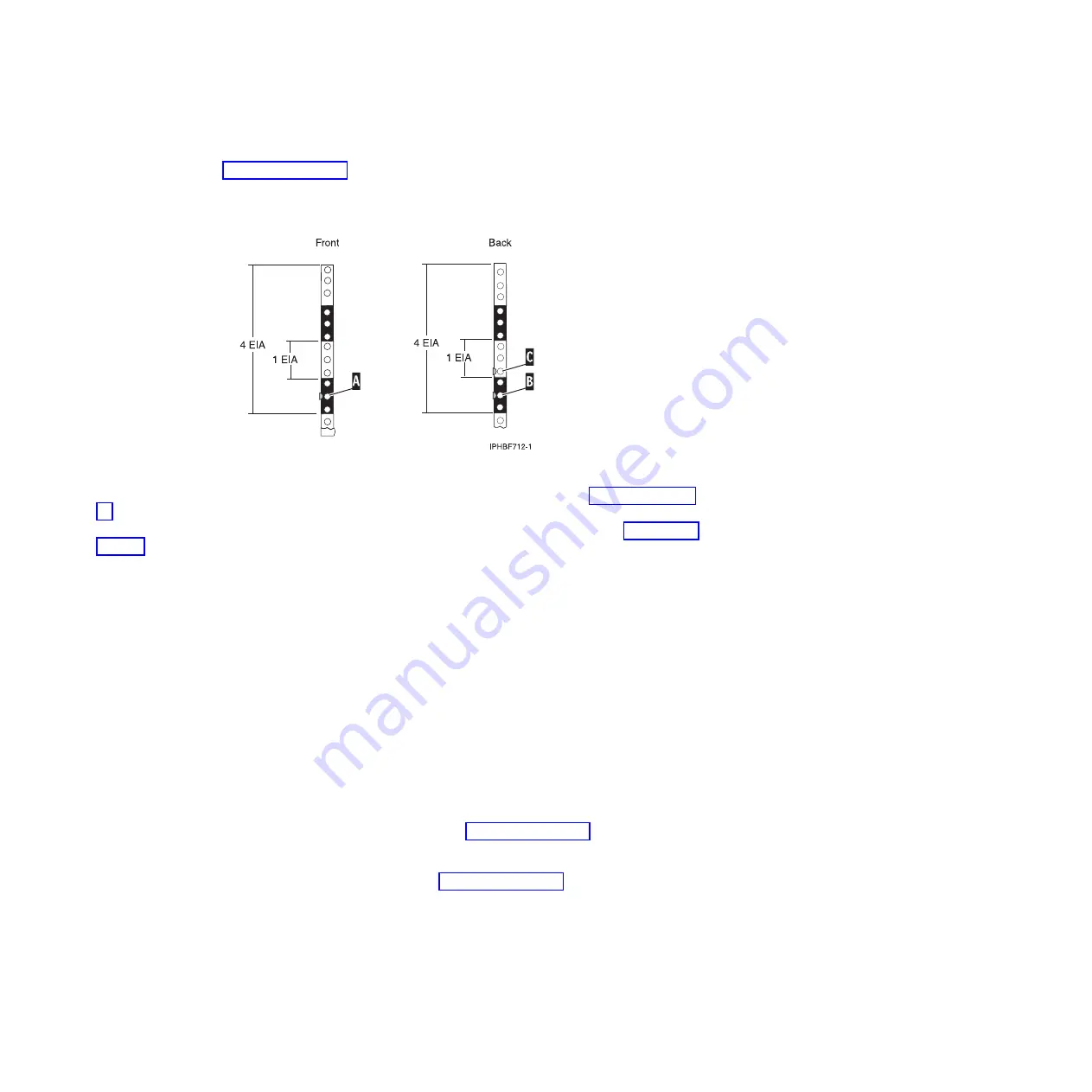
Place another self-adhesive dot next to the middle hole of the bottom EIA unit on the left side of the
rack
(A)
as shown in Figure 21 on page 29.
4.
Go to the back of the rack. On the right side, find the EIA unit that corresponds to the bottom EIA
unit marked on the front of the rack.
5.
Place a self-adhesive dot at the middle hole of the bottom EIA unit
(B)
as shown in Figure 21 on page
6.
Place a self-adhesive dot at the bottom hole of the next (higher) EIA unit
(C)
as shown in Figure 21 on
7.
Mark the corresponding holes on the left side of the rack.
Attaching 8203-E4A, 8261-E4S, 9407-M15, or 9408-M25 mounting
hardware to the rack
You might need to attach the mounting hardware to the rack. Use this procedure to perform this task.
This section provides information related to safety and reliable operation. You can also find illustrations
of the related hardware components showing how these components relate to each other.
Attention:
To avoid rail failure and potential danger to yourself and to the unit, ensure that you have
the correct rails and fittings for your rack. If your rack has square support flange holes or screw-thread
support flange holes, ensure that the rails and fittings match the support flange holes used on your rack.
Do not install mismatched hardware using washers or spacers. If you do not have the correct rails and
fittings for your rack, contact your IBM reseller. Also, to install the rails correctly, perform each task in
the following order.
To install the rack-mounting hardware into the rack, complete the following steps:
1.
With the right rail, twist the latch assembly release tab
(A)
in Figure 36 on page 43. Then slide tab
(B)
back to the retracted position and lock the latch assembly. The back-alignment pins must be fully
retracted.
2.
Insert the right side rail front-alignment pin as shown in Figure 36 on page 43, into the rack front
flange hole identified by the self-adhesive placement dot that you previously installed. Have a
second person hold the rail securely in the front hole.
Figure 35. Marking holes on the front and back of the rack frame
42
Installing into a rack
Содержание 0551
Страница 1: ...Power Systems Rack rack features and installing systems or expansion units into a rack ...
Страница 2: ......
Страница 3: ...Power Systems Rack rack features and installing systems or expansion units into a rack ...
Страница 8: ...vi Installing into a rack ...
Страница 12: ...2 Installing into a rack ...
Страница 34: ...24 Installing into a rack ...
Страница 118: ...108 Installing into a rack ...
Страница 126: ...116 Installing into a rack ...
Страница 130: ...120 Installing into a rack ...
Страница 136: ...4 Remove the latch bracket from the system unit Figure 124 Removing the retaining screws 126 Installing into a rack ...
Страница 148: ...138 Installing into a rack ...
Страница 164: ...154 Installing into a rack ...
Страница 174: ...3 Close the front rack door 164 Installing into a rack ...
Страница 181: ......
Страница 182: ... Printed in USA ...


