INSTALLATION AND OPERATION INSTRUCTIONS
8
IBC INDIRECT WATER HEATERS - ALL MODELS
3) - Piping
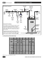
A. Domestic water piping - See Section 8, Mechanical Drawing # 6
1. Drain the domestic water system.
• Shut off the cold water supply at the main shutoff valve.
• Open one or more faucets to relieve the pressure. Open the system drain,
leaving the faucets open.
2. Position the water heater in the final location.
3. Connect the cold water supply piping.
• Install piping onto cold inlet connection -
• Connect to cold water supply connection using the following suggested
components where applicable: A union, a heat trap, a shut-off valve, an
expansion tank, a back flow preventer, a vacuum breaker and a filter
(recommended to prevent sediment buildup).
4. Connect the domestic hot water piping.
• Install piping on to hot water supply connection using a union, a heat trap,
and a shut-off valve.
• Pipe the relief valve discharge so that the discharge from the valve will exit
only within 6 inches above, or at any distance below, the structural floor, and
cannot contact any live electrical part. The discharge opening must not be
blocked or reduced in size under any circumstances.
5. Fill the water heater tank.
• Open all faucets to allow air to purge from the tank and piping. Remove
screens on faucets.
• Open the domestic hot water shut-off valve.
• Slowly open the cold water inlet shut-off valve.
• Purge all of the air from the domestic water system. Allow water to run so the
tank is completely purged of any debris. Run the water long enough so that it
runs clear and to change at least one tank volume change past full. Close all
faucets. Reinstall all of the screens in the faucets.
• Check the system for leaks. Repair as required.
B. Boiler water piping. See Figures in Section 8.
1. Determine where the boiler, the space heating, and the water heater
connections should be made based on the type of piping system that is either
in place, or is to be installed for a new hydronic system installation. See
Schematic drawings in Section 8 for direction.
2. It is recommended that minimum size 1” pipe be used on the water heater
zone to ensure adequate flow, larger sizes (80 and 115 models) min 1 1/4”.
Zone Circulator System
For space heating systems that use Zone Circulators only;
refer to Mechanical
Drawings #1, #2 and #3 in Section 8 of this manual.
The water heater connection
labeled “BOILER SUPPLY” should be piped to the boiler supply piping after
the air purger and before the space heating takeoffs - for primary/secondary
systems,
see Mechanical Drawing #1
- parallel piping,
see Mechanical drawings
#2 and #3.
Mount the water heater circulator as close as is practicable to the
water heater, and make sure the flow arrow points toward the water heater. The
use of shut-off valves is recommended for future service convenience.
NOTE
Installers should inquire of
local water purveyors as to
the suitability of their supply
for use in hydronic heating
systems.
If water quality is questionable,
a local water treatment expert
must be consulted for testing,
assessment and, if required,
treatment.
Alternatively, water or hydronic
fluid of known quality can be
brought to the site.
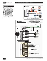
WARNING
Do not use automotive-type
ethylene or other types of
automotive glycol antifreeze,
or undiluted antifreeze
of any kind on the boiler
water side of the system.
This may result in severe
boiler or tank damage. It
is the responsibility of the
Installer to ensure that glycol
solutions are formulated to
inhibit corrosion in hydronic
heating systems of mixed
materials. Improper mixtures
and chemical additives may
cause damage to ferrous and
non-ferrous components as
well as non-metallic, wetted
components, normally found
in hydronic systems.
Ethylene glycol is toxic, and
may be prohibited for use
by codes applicable to your
installation location. For
environmental and toxicity
reasons, IBC recommends
only using non-toxic
propylene glycol, and non-
toxic boiler water additives of
any kind.


