


INSTALLATION AND OPERATION INSTRUCTIONS
6
IBC INDIRECT WATER HEATERS - ALL MODELS
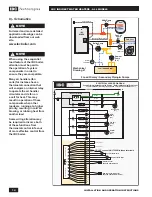
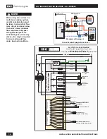
3. Zone Valves – The space heating zones use zone valves for each zone, and
the water heater is controlled with an additional zone valve. Select a valve
with a low pressure drop, and adequate pipe size to assure minimum flow.
See Section 8, Mechanical Drawing #4.
B. Priority or Non-Priority for Hot Water
Option 1 – Priority.
The demand for space heating is interrupted until the hot
water demand is satisfied. This option provides the maximum delivery of hot wa-
ter. IBC boilers are easily configured to operate the Hot Water as a priority load.
Priority is recommended when:
1. The boiler output is less than 100,000 Btu per hour, or
2. The boiler output required to satisfy the hot water demand is more than 50%
of the boiler output needed to satisfy the space heating demand, or
3. When an interruption in space heating can be tolerated during long domestic
hot water draws.
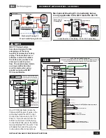
The preferred strategy when using an IBC boiler is to use a load circulator for
domestic hot water and the IBC controller to switch the circulator on and off using
the IBC control logic and sequential priority hardware. In most cases the delay
in space heating will not be noticed because of the rapid recovery of the water
heater. Certain water heater malfunctions, such as a failed sensor or circulator,
might delay space heating temporarily until the IBC controller internal logic takes
over and operates all loads equally until the malfunction is corrected.
Option 2 – Non-Priority.
The boiler output is divided between space heating
and water heating. Heating of domestic hot water can be reduced during simul-
taneous space and water heating demands. The maximum amount of reduction
depends on the boiler output, the number of space heating zones calling, the
space heating target water temperature, and the amount of boiler water flow split
between the space heating and zones and the water heater zone. Most IBC boil-
ers are now shipped with “Load Pairing” software that can provide DHW priority
with simultaneous space heating allowed during moderate heating demands.
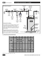
C. Locating the water heater.
The water heater should be located in an area where water leakage from the tank
or connections will not result in damage to areas adjacent to the water heater or
to lower floors of the structure. When such a location can not be avoided, a suit-
able drain pan must be installed under the water heater, and the drain pan must
be connected to a drain.
The water heater should be installed as close to the boiler as is practical for easy
access for service. The unit is designed for installation on combustible flooring
and in alcoves, closets, etc.
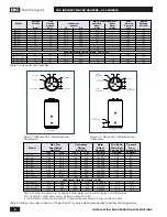
SURFACE
DISTANCE FROM
COMBUSTIBLES FOR SERVICE
Front
1"
30"
Rear, Right and Left Sides
1"
3"
Top
6”
6”
Bottom
0"
0”
Table 3: Clearances from heater jacket
WARNING
During operation, the T&P
relief valve may discharge
large amounts of steam and/
or hot water. Therefore, to
reduce the potential for bodily
injury and property damage,
a discharge line MUST be
installed that it:
1. is connected from the valve outlet
with no intervening valve and
directed downward to a safe point of
discharge.
2. allows complete drainage of both the
valve and the discharge line.
3. is independently supported and
securely anchored so as to avoid
applied stress on the valve.
4. is as short and straight as possible
5. terminates freely to atmosphere
where any discharge will be clearly
visible and is at no risk of freezing.
6. terminates with a plain end which is
not threaded.
7. is constructed of a material suitable
for exposure to temperatures of
375°F or greater.
8. is, over its entire length, of a pipe size
equal to or greater than that of the
valve outlet.
DO NOT CAP, PLUG OR OTHERWISE
OBSTRUCT THE DISCHARGE PIPE
OUTLET!
CAUTION
To avoid water damage from
leaks, a drain pan should
be installed under the water
heater unless it is installed in
a location where leaks will not
cause property damage - see
Drawing # 6.
If the discharge from a T&P
relief valve cannot be directed
into a drain or to an area
where water damage will not
occur, a drain pan capable
of draining away the full,
continuous discharge flow
of the relief valve should be
installed.


