IBC 30 Скачать руководство пользователя страница 12

INSTALLATION AND OPERATION INSTRUCTIONS

12

IBC INDIRECT WATER HEATERS - ALL MODELS

7) - Troubleshooting

6.  Using a funnel, pour one gallon of commercial ice maker cleaning solution 

into the tank through the relief valve opening. Follow the instructions, 

cautions, and warnings supplied with the cleaning solution.

7.  Turn on the power to the boiler and water heater, program the IBC control 

to its highest DHW temp. setting, and allow the boiler to heat the water until 

the control is satisfied. If the boiler control is not satisfied after 45 minutes 

of operation, program the IBC DHW control setting to its lowest temp.

8.  Allow the heated solution to set in the tank 30 minutes.
9.  Drain the tank completely using fittings and hoses, as required, to reach a 

drain.

10. Fill the water heater tank with fresh, cold, water and drain it completely. 

Repeat filling and draining at least three (3) times to flush all of the 

cleaning solution from the tank.

11.  Reinstall the relief valve and the drain piping.
12. Open the cold water supply and fill the tank with water. Purge the air from 

the tank and the piping by opening the cold and hot water faucets in the 

house.

13. Return the IBC DHW control setting to the temperature noted in Step 2.
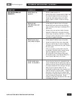
SYMPTOM

DIAGNOSIS

REMEDY

WATER AT FAUCETS TOO 

HOT

IBC boiler DHW 

temperature setting 

too high

•  Reduce the DHW Tank Set Point 

temperature in the Configure Load Menu 

DHW temperature 

sensor problems 

giving false reading to 

IBC Control

•  Sensor has fallen from well
•  Sensor giving incorrect resistance reading
•  sensor connected to Therm terminals 

instead of DHW S terminals

•  improper 3rd party sensor installed in well

•   

WATER AT FAUCETS TOO 

COOL

IBC boiler DHW 

temperature setting 

too low

•  Increase the DHW Tank Set Point 

temperature in the Configure Load Menu

IBC boiler DHW 

Maximum Supply 

Temp. setting too low

•  Make sure the Maximum Supply Temp. 

setting is at least 10°F higher than the DHW 

Supply Setpoint PLUS 1/2 of the Supply 

Diff’l Temp setting.

Содержание 30

Страница 1: ...IBC 115 HO C FOR SINGLE WATER HEATER INSTALLATIONS For service or repairs to the water heater call your heating contractor Your water heater has been manufactured to provide years of service In order...

Страница 2: ...n hazardous conditions that could result in property damage and injury to occupants which in extreme cases might result in death When using electrical appliances basic safety precautions to reduce the...

Страница 3: ...es for Hot Water Supply Systems ANSI Z21 22 latest edition This valve must be marked with a maximum set pressure not to exceed the marked working pressure of the water heater Install the valve into an...

Страница 4: ...400 14 0 6 6 T P VALVE 1 1 4 NPT BOILER SUPPLY 1 1 4 NPT BOILER RETURN 1 1 2 NPT DOM COLD INLET SENSOR WELL DRAIN C UNITS 8 0 8 0 9 5 3 4 NPT RECIRC PORT 1 1 2 NPT HOT OUTLET T P VALVE BOILER SUPPLY...

Страница 5: ...low through the water heater coil and the pressure drop at minimum flow Calculate the pressure drop across all piping and fittings connected to the water heater zone Be sure to include all zone valves...

Страница 6: ...software that can provide DHW priority with simultaneous space heating allowed during moderate heating demands C Locating the water heater The water heater should be located in an area where water le...

Страница 7: ...supply line to the heater strip back to the tank or nearest mains piping and cap off If oil heating system is to be abandoned completely ensure proper removal and disposal of old oil tank and remainin...

Страница 8: ...g system that is either in place or is to be installed for a new hydronic system installation See Schematic drawings in Section 8 for direction 2 It is recommended that minimum size 1 pipe be used on...

Страница 9: ...tallation Manual for the boiler as well Temperature Sensor The Temperature Sensor supplied with the IBC Water Heater is an NTC Thermistor type with a resistance of 10 000 ohms at 25 C and 3892 IBC doe...

Страница 10: ...HW operation if the DHW Priority setting is higher than the other heating loads Temperature Adjustment The tank sensor controls the maximum water temperature in the water heater If it is set too high...

Страница 11: ...e frequent service Depending on water conditions a varying amount of sediment may collect in the tank Levels requiring service are indicated by a small temperature difference between the boiler supply...

Страница 12: ...to flush all of the cleaning solution from the tank 11 Reinstall the relief valve and the drain piping 12 Open the cold water supply and fill the tank with water Purge the air from the tank and the pi...

Страница 13: ...n Follow steps for Boiler does not operate Check for 24VAC at the zone valve while there is a call for heat if correct voltage is available and connections are good replace the zone valve If the zone...

Страница 14: ...with IBC Water Heater Interlock 1 Interlock 2 Therm 1 Therm 2 Therm 3 Outdoor S Indoor S 2nd Loop S DHW S Boiler Net Ext Cont White Green Black Fuse 5A Fuse 5A Fuse 5A Fuse 5A G1 DHW Pump P2 Fan Coil...

Страница 15: ...20 115 Pumps Only IBC SL 20 115 BOILER IBC DHW Domestic Hot Water Sensor DHW Pump P1 Fan Coil Pump P2 Outdoor Sensor Fan Coil Thermostat Mechanical Drawing 3 FAN COIL NOTE IBC VFC Series boilers have...

Страница 16: ...op S DHW S Boiler Net Ext Cont White Green Black Fuse 5A Fuse 5A Fuse 5A Fuse 5A G1 G2 G3 G4 G5 G6 G7 G8 O1 O2 O3 O4 O5 O6 O7 O8 O9 O10 O11 O12 O13 O14 O15 O16 O17 O18 O19 O20 O21 O22 Auxiliary Interl...

Страница 17: ...iping w DHW Pump and Baseboard system Zone Valves Domestic Hot Water Sensor BB Zone 1 Thermostat Mechanical Drawing 5 BB Zone 1 Valve ZV1 BB Zone 2 Valve ZV2 BB Zone 3 Valve ZV3 Zone Valve end switch...

Страница 18: ...Well Drain Valve and Temperature Pressure Relief Valve An IBC Temperature Sensor is shipped loose with the tank to be inserted into the Temperature Well and wired to the IBC Boiler Control Board on Te...

Страница 19: ...115 F 140 F 115 F 140 F 115 F 140 F 115 F 50 000 139 164 67 92 170 195 67 92 60 000 152 183 80 111 183 214 80 111 80 000 179 219 107 147 210 250 107 147 100 000 205 256 133 184 236 287 133 184 120 000...

Страница 20: ...115 F 140 F 115 F 140 F 115 F 140 F 115 F 50 000 139 164 67 92 170 195 67 92 60 000 152 183 80 111 183 214 80 111 80 000 179 219 107 147 210 250 107 147 100 000 205 256 133 184 236 287 133 184 120 000...

Страница 21: ...21 INSTALLATION AND OPERATION INSTRUCTIONS IBC INDIRECT WATER HEATERS ALL MODELS DATE LICENSED CONTRACTOR DESCRIPTION OF WORK DONE Service Record Notes...

Страница 22: ...ATION AND OPERATION INSTRUCTIONS 22 IBC INDIRECT WATER HEATERS ALL MODELS IBC Technologies Inc 1445 Charles Street Vancouver BC Canada V5L 2S7 Tel 604 877 0277 Fax 604 877 0295 www ibcboiler com 120 1...

Отзывы: