background image


MAN-072 

25                                                                     


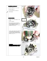
OPENING THE STARTER MOTOR 


-   UNSCREW THE M4 SCREW FIXING THE INPUT 

CABLE  


    (See Fig.6) 


   (SCREWDRIVER)                                               


- UNSCREW THE 3 M5 

“C” 

SCREWS (See Fig.7) 


   (SCREWDRIVER)                                                


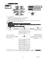
Fig.1 

Fig.6 

Fig.7 

Содержание ReedJet AUS 100cc-TaG

Страница 1: ...MAN 033 REEDJET AUS 100cc TaG 01 11 04 INSTALLATION MANUAL...

Страница 2: ...of steel alloy hardened and tempered as is the connecting rod which runs on roller bearings The ignition includes a 2 pole stator rotor an H T coil a starter relay and complete wiring harness The spa...

Страница 3: ...ional RPM limits the motor not included RPM Limiter Max RPM 1 15 000 RPM CONTENT OF THE ENGINE PACKAGE EXHAUST GRUOP Quantity x Exhaust muffler spring 2 x Exhaust manifold no restricted restricted 19m...

Страница 4: ...MAN 072 3 ACCESSORIES EXHAUST GROUP COPERCHIO FRIZIONE INLET SILENCER FILTER TILLOTSON CARBURETTOR SPARKPLUG KIT CLUTCH COVER H T COIL PUSH BUTTONS BRACKET WIRING HARNESS BATTERY SUPPORT KIT...

Страница 5: ...2 digits numbers AU and 2 other digits numbers there can be exceptions in some special cases Other numbers stamped on the crankcase or other surfaces of the motor refer to various manufacturing proce...

Страница 6: ...it is at care of the assembler to follow these instructions The final customer in this case can skip this section and can start reading from section 4 Whenever the engine or a component is disassemble...

Страница 7: ...E THAT THE EXHAUST GASKET IS IN SEAT AND INSTALL THE EXHAUST MANIFOLD SEE FIG 1 INSERT THE 2 ELASTIC WASHERS 8mm SUGGESTION PUT THE ENGINE IN HORIZONTAL POSITION AND PLACE THE WASHERS IN THEIR SEAT HE...

Страница 8: ...4 8 mm Torx T20 INSTALL THE SUPPORT BRACKET AND THE TWO SCREWS SCREWDRIVER 4 8 mm Torx T20 SEE FIG 7 INSTALL THE INTAKE SILENCER SUPPORT 2x SCREWS M5x10 ALLEN WRENCH 3 mm SEE FIG 8 POSITIONING CARBUR...

Страница 9: ...THE CHASSIS CONNECT THE FUEL FEED HOSE TO THE INLET FITTING ON THE CARBURETTOR CAP SEE FIG 10 2 4 PREPARATION AND INSTALLATON OF THE ENGINE MOUNT NOTE ALL THE DIMENSIONS IN MILLIMETERS DRILL 4 HOLES D...

Страница 10: ...IN IS INSTALLED AND PROPERLY ALIGNED CHECK THE ALIGNMENT OF THE ENGINE SPROCKET AND THE AXLE SPROCKET WITH A STRAIGHT EDGE SEE FIG 12 INSTALL THE CHAIN PITCH 7 775 SEE FIG 13 MOVE THE ENGINE ON THE RA...

Страница 11: ...THE H T COIL SEE FIG 16 TIGHTEN THE 3 SCREW AT 8 10 Nm ATTENTION ALWAYS MAKE SURE THAT THE GROUND CABLE ALWAYS CONNECTS THE COIL WITH THE ENGINE AN INADEQUATE GROUNDING COULD DAMAGE THE IGNITION BEYON...

Страница 12: ...MALE KEY 5mm PLACE THE BATTERY SUPPORT THE PUSH BUTTONS BRACKET BETWEEN THE CLAMP AND THE BATTERY SUPPORT SEE FIG 19 THEN TIGHTEN THE COMPONENTS WITH A 10mm SOCKET WRENCH AFTER TIGHTENING THE BATTERY...

Страница 13: ...FIG 22 NOTE THE 2 START BUTTON FASTONS CAN BE INVERTED THIS DOES NOT CAUSE WORKING PROBLEMS CONNECT THE BATTERY CABLES TO THE FASTONS AND TIGHTEN THE STRAP ON THE CABLES SEE FIG 23 CONNECT THE STARTE...

Страница 14: ...P CABLE TO THE FEMALE FASTON CONNECTOR OF THE INGNITION SEE FIG 28 CONNECT THE FEMALE FASTON OF THE INGNITION CABLE ON THE H T MALE FASTON SEE FIG 29 SCREW THE SPARK PLUG CAP ON THE COIL HIGH VOLTAGE...

Страница 15: ...X THE INLET SILENCER WITH THE DEDICATED CLAMP ON THE CHASSIS TUBE SEE FIG 32 33 2 9 ASSEMBLY OF THE EXHAUST SYSTEM NOTE SEE SECTION 3 8 FOR THE WARNINGS ON EXHAUST SYSTEM ASSEMBLY THE EXHAUST SILENCER...

Страница 16: ...ded oils WLADOIL RACING K2T SHELL ADVANCE RACING M ELF HTX 909 ERG K KART FORMULA Once the tank has been filled make sure that the fuel flows to the carburettor before starting the engine Avoid pump f...

Страница 17: ...O Start the engine and warm it If the if RPM is too high set the screw l counterclockwise untill the clutch is disengaged If RPM decreases Unscrew counterclockwise untill max RPM is reached Unscrew j...

Страница 18: ...ng time but to alternate it 4 Increase the speed driving some laps for about 5 minutes with acceleretor fully opened on circuit twisty parts and enrich the carburation at half straight cover with the...

Страница 19: ...test or race and replace it if necessary A bad alignment of the engine sprocket with the axle sprocket or chain grease lack can irreparably damage the sprocket When it is necessary to check the clutch...

Страница 20: ...3 Remove the retainer nut 1 nut M10 Ring wrench 17 mm 4 Remove the external washer the complete drum with roller cage the internal washer 5 With the starter wheel locking tool in place remove the 20x1...

Страница 21: ...ng tool in place tighten the drum retainer nut nut M10 Starter wheel locking tool S 884 Ring wrench 17 mm torque at 30 40 Nm 7 Reassemble the clutch cover 3 screws TCEI M6 Allen wrench 5mm T type torq...

Страница 22: ...re attaching a correspondence list among several brands according to the thermal degree which represents the capacity of the spark plug to dissipate the inside heat The colour of the various parts of...

Страница 23: ...it is exceed In case the user wishes to optimize the sprocket ratio on the track in order to achieve the best possible performance and without overloading the engine follow the under shown recommendat...

Страница 24: ...R SUPPORT See Fig 1 5mm ALLEN WRENCH T TYPE REMOVE THE ADDITIONAL STARTER SUPPORT 3 SCREWS M6X25 See Fig 2 5mm ALLEN WRENCH T TYPE REMOVE THE STARTER SUPPORT 4 SCREWS M6x35 See Fig 3 5mm ALLEN WRENCH...

Страница 25: ...MAN 072 25 OPENING THE STARTER MOTOR UNSCREW THE M4 SCREW FIXING THE INPUT CABLE See Fig 6 SCREWDRIVER UNSCREW THE 3 M5 C SCREWS See Fig 7 SCREWDRIVER Fig 1 Fig 6 Fig 7...

Страница 26: ...ROTOR FROM THE STARTER MOTOR HEAD see Fig 9 ATTENTION WHEN EXTRACTING THE ROTOR THE BRUSHES MAY SPRING OUT FROM THEIR SEATS REPLACING THE BRUSH A UNSCREW THE 2 SCREWS M4 D RETAINING THE PLATE E see Fi...

Страница 27: ...SPRINGS REMOVE THE BRUSH MAKING PRESSURE ON THE TIN PLATE TERMINAL EXTERNALLY see Fig 13 INSTALL NEW BRUSH TERMINAL See Fig 14 PLACE THE LITTLE RUBBER CAP ON THE TERMINAL REINSTALL THE PLATE AND FIX I...

Страница 28: ...SH IN PLACE BY PRESSING TOWARDS THE OUTER AND CLAMP IT WITH AN IRON WIRE BENT AS A HOOK REPEAT THE SAME PROCEDURE TO INSTALL THE BRUSH B See Fig 17 INSTALL THE ROTOR BETWEEN THE BRUSHES AND CHECK THAT...

Страница 29: ...ES FREELY CONNECT THE INPUT WIRING TO THE STARTER WITH THE SCREW M4 see Fig 22 SCREWDRIVER ASSEMBLING THE STARTER PLACE THE STARTER IN SEAT see Fig 23 PUT SOME OIL ON THE O RING TO EASE INSTALLATION N...

Страница 30: ...s and charge Cables and connectors Check status and restore the connections Grounding engine Check status and restore the connections Battery support bracket and clamps Check torques After each use Ba...

Страница 31: ...gine starts but turns off after a short time Bad harness connections Check connectors Bad carburettor setting screw I Check carburettor retting see sect 5 The starter turns also after releasing the st...

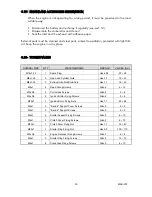
Страница 32: ...k Plug Hex 20 8 20 26 M8x1 25 5 Head and Cylinder Nuts Hex 13 18 22 M8x1 25 2 Exhaust manifold Stud Nuts Hex 13 18 22 M6x1 4 Reed Group Screws Allen 5 8 10 M5x0 8 3 Coil Attack Screws Allen 4 5 6 M5x0...

Страница 33: ...MAN 072 36 1 Start Stop button 2 Battery 3 Ignition adapter 4 Starter 5 H T Coil 6 Ignition 3 21 WIRING DIAGRAM...

Отзывы: