


15
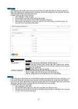
1000Mbps Gigabit Ethernet Collision Domain Table
Maximum 1000Base-T Gigabit Ethernet Cable Length
Cable Type
Maximum cable length
Connector
Category 5, 5e or 6 100-ohm UTP or STP
100m (328 ft.)
RJ-45
Maximum 1000BASE-SX Gigabit Fiber Cable Lengths
Fiber Size
Fiber Bandwidth
Maximum Cable Length
Connector
62.5/125 micron
multimode fiber
160MHz/km
200HHz/km
220m (722 ft.)
275m (902 ft.)
LC
LC
50/125 micron
multimode fiber
400 MHz/km
500 MHz/km
500m (1641 ft.)
550 m (1805 ft.)
LC
LC
Maximum 1000Base-LX/LHX/XD/ZX Gigabit Fiber Cable Length
Fiber Size
Fiber Bandwidth
Maximum Cable length
Connector
9/125/ micron
single-mode fiber 1310nm
N/A
10km (6.2 miles)
LC
9/125/ micron
single-mode fiber 1550nm
N/A
30km (18.64 miles)
50km (31.06 miles)
LC
LC
Maximum 1000BASE-LX Single Fiber Gigabit Fiber Cable Length
Fiber Size
Fiber Bandwidth
Maximum Cable Length
Connector
Single-Mode
N/A
20km (12.42 miles)
BIDI
TX-1310nm
N/A
20km (12.42 miles)
LC
RX-1310nm
N/A
20km (12.42 miles)
LC
Cable labelling and Connection Records
When planning a network installation, it is essential to label the opposing ends of cables and to record where each cable
is connected. This will allow the user to easily locate inter-connected devices, isolate faults and change your topology
without wasting time unnecessarily. To best manage the physical implementations of the network follow these
guidelines.
•
Clearly label the opposing ends of each cable.
•
Using your building’s floor plans, draw a map of the location of all network-connected equipment. For each
piece of equipment, identify the devices to which it is connected.
•
Note the length of each cable and the maximum cable length supported by the switch ports.
•
For ease of understanding use a location based key when assigning prefixes to your cable labeling.
•
Use sequential numbers for cables that originate from the same device.
•
Differentiate between racks by naming accordingly.
•
Label each separate piece of equipment.
•
Display a copy of your equipment map including keys to all abbreviations at each equipment rack.
Troubleshooting
Most problems are caused by the following situations. Check for these items first when starting your troubleshooting:
Connecting to devices that have a fixed full duplex configuration.
•
The RJ45 ports are configured as “Auto”. That is, when connecting to attach devices, the switch will operate in
one of two ways to determine the link speed and the communication mode (half duplex or full duplex).
•
If the connected device is also configured to Auto, the switch will automatically negotiate both link speed and
communication mode.
•
If the connected device has a fixed configuration, for example 100Mbps, at half or full duplex, the switch will
automatically sense the link speed, but will default to a communication mode of half duplex.
•
Because the S243 Switch behaves in this way (in
compliance with the IEEE802.3 standard
), if a device
connected to the switch has a fixed configuration at full duplex, the device will not connect correctly to the
switch. The result will be high error rates and very inefficient communications between the switch and the
device. Make sure all devices connected to the S243 Switch are configured to auto negotiate, or are configured
to connect at half duplex (all hubs are configured this way.)
Faulty or loose cables.
•
Look for loose or obviously faulty connections. If they appear to be OK, make sure the connections are snug. If
that does not correct the problem, try a different cable.
•


