background image

C h a p t e r   1 7

Hardware Information

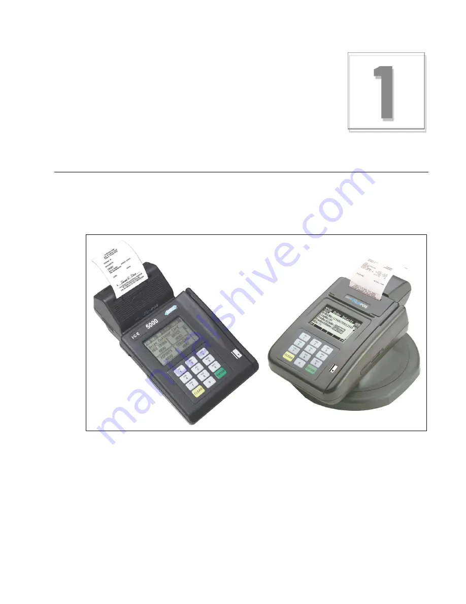
This chapter provides important information to properly set up and test both the ICE 5000 and 5500 
terminals. To prevent damage to the POS terminals and possible personal injury, be sure to read this 
document before installing the ICE terminals.

Figure 1-1. ICE 5000 and 5500 terminals

Содержание ICE 5000

Страница 1: ...ICE 5000 5500 Hardware and Installation Operators Manual Document Version 1 0 Revision B Date 03 07 2000...

Страница 2: ......

Страница 3: ...om furnishes in this publication is believed to be accurate and reliable However the corporation assumes no responsibility for its use and reserves the right to make changes to the publication at any...

Страница 4: ...umber of devices you may connect to your line contact your local telephone company to determine the maximum REN for your calling area NOTE REN is associated with loop start and ground start ports Do n...

Страница 5: ...uipment Any repairs or alterations to this equipment or any equipment malfunctions may cause the telephone communications company to request that the user disconnect the equipment Users should ensure...

Страница 6: ......

Страница 7: ...yboard 1 3 PIN Pad 1 3 Touch Screen Display 1 4 Magnetic Stripe Read Card Reader 1 4 Thermal Printer 1 4 Auto Receipt Cutter 1 5 High Speed Modem 1 5 Memory 1 5 Power Requirements 1 5 Dimensions 1 5 C...

Страница 8: ...Wireless POS Terminal Interface Function Blocks 4 1 Operation 4 1 Instructions to the User 4 2 Basic System 4 3 Basic System Installation 4 3 Extending Basic Coverage Area 4 4 Installing Extended Basi...

Страница 9: ...Figure 3 1 ICE 5000 printer paper door open 3 5 Figure 3 2 ICE 5000 printer paper installation 3 6 Figure 3 3 ICE 5000 Printer paper installation complete 3 6 Figure 3 4 ICE 5500 printer paper door o...

Страница 10: ......

Страница 11: ...bles Chapter 1 Hardware Information Table 1 1 Terminal dimensions 1 5 Chapter 2 Installation Procedures Table 2 1 Self test and diagnostics with software loaded 2 4 Table 2 2 Memory page states 2 4 Ta...

Страница 12: ......

Страница 13: ...on The guide contains the following chapters n Chapter 1 Hardware Information General descriptions of hardware required to operate the ICE 5000 or 5500 terminal n Chapter 2 Installation Procedures Ste...

Страница 14: ...t statements draw attention to information crucial to using the product successfully Pay special attention to Important statements Procedures Numbered procedures have a special graphic appearing in th...

Страница 15: ...le From the Term Master main menu click Network Definitions Caution and Warning boxes When you see a Caution or Warning message read the information promptly and carefully before proceeding The format...

Страница 16: ......

Страница 17: ...important information to properly set up and test both the ICE 5000 and 5500 terminals To prevent damage to the POS terminals and possible personal injury be sure to read this document before install...

Страница 18: ...ar a static strap and are grounded to the POS products To ensure protection of the telecommunications port against lightning damage this product requires connection to the building protective earthing...

Страница 19: ...to meet various cardholder needs n Audible signals that notify the cardholder of the action being taken Figure 1 2 Standard keyboard PIN Pad The ICE 5000 and 5500 are both a terminal and a PIN pad The...

Страница 20: ...iguration for the ICE 5000 and 5500 terminals includes a 1 7 inch by 2 6 inch graphic dot matrix touch screen that is capable of character graphics and signature display While in character mode the di...

Страница 21: ...technology to achieve 9600 bps throughput and 0 5 second training times at a cost that is comparable to the cost of 2400 bps modems FastPOS results in faster transactions and lower transaction costs...

Страница 22: ......

Страница 23: ...tep To power up the ICE terminal 1 Connect the 24 Vdc power cable from the AC Adaptor to the three pin terminal socket labeled POWER on the back panel of the ICE 5000 or 5500 terminals 2 Plug the AC A...

Страница 24: ...le into the opening labeled LINE on the back panel of the ICE 5000 or 5500 terminal Power socket WARNING Disconnect the AC electric power before replacing the printer module Do not use an adapter a po...

Страница 25: ...e that the telephone line cable latches are firmly locked into the jacks on both the ICE 5000 or 5500 terminal and wall receptacle Figure 2 3 ICE 5000 line port Figure 2 4 ICE 5500 line port Line port...

Страница 26: ...one of the states shown in the following table Table 2 1 Self test and diagnostics with software loaded Description Terminal response Software Software name and version DLL Tracks the number of downlo...

Страница 27: ...ription Terminal response T5KBOOT Boot program name XXX Boot program release T5KBOOTXXX WAIT SELF TEST The memory page status indicates that no program is loaded MEMORY PAGE STATUS BOOT XXXX 01 FFFFFF...

Страница 28: ......

Страница 29: ...parameters the ICE 5000 or 5500 uses to communicate with Term Master When the configuration is complete the terminal is able to receive the terminal application software Step by Step To configure the...

Страница 30: ...B C D E F CANCEL CLEAR ENTER 4 Type the NMS number then touch or press Enter MERCHANT PROGRAMMING DIAL 0 TONE 1 PULSE A B C D E F CANCEL CLEAR ENTER 5 Type 0 for tone dialing or 1 for pulse dialing th...

Страница 31: ...s Step by Step To load a program into the ICE terminal Step Action Terminal response The Idle prompt appears PLEASE INITIALIZE OR CALL HELP PE 0 RESTART 1 MERCHANT PROGRAMMING 2 PROGRAM LOAD 3 CLEAR P...

Страница 32: ...automatically connects to the initialization host to receive the downloading of the initialization parameters known as the terminal profile Step by Step To initialize an ICE terminals Step Action Term...

Страница 33: ...r into the termial read the following steps carefully Step by Step To load the printer paper in the ICE 5000 1 Open the paper door on the back of the ICE 5000 printer Figure 3 1 ICE 5000 printer paper...

Страница 34: ...oceed with step 4 Otherwise proceed to step 9 Figure 3 2 ICE 5000 printer paper installation Figure 3 3 ICE 5000 Printer paper installation complete 4 Touch Press here for Menu on the terminal display...

Страница 35: ...f the ICE 5500 printer Figure 3 4 ICE 5500 printer paper door open 2 Place the paper roll into the printer paper holder make sure the printer paper unrolls from under the roll not over the top and has...

Страница 36: ...y touch Terminal Menu 5 Touch the arrow The Terminal Main menu prompt appears 6 Touch Setup The Setup menu appears 7 Touch Printer The Printer prompt appears 8 Touch Paper Feed The Paper Feed menu app...

Страница 37: ...up The Setup menu appears d Touch Printer The Printer prompt appears e Touch On Off The Printer Toggle menu prompt appears The menu displays Printer is disabled Enable f Touch Yes The terminal changes...

Страница 38: ......

Страница 39: ...es to the ICE 5000 n Terminal transceiver interface Hypercom model FTI01 or for use with a single terminal transceiver a Hypercom adapter cable P N 810170 001 n Terminal transceiver Hypercom model FXV...

Страница 40: ...on the user is encouraged to try to correct the interference by one or more of the following measures n Reorient or relocate the receiving antenna n Increase the separation between the equipment and...

Страница 41: ...tem 1 Ensure the host terminal is properly configured and connected for use as a standard POS terminal See the manual provided with the host POS terminal 2 Insert the male end of the single unit Hyper...

Страница 42: ...adding a terminal transceiver interface and an additional terminal transceiver Figure 4 2 Extending basic coverage Installing Extended Basic Coverage Area Use this procedure for installing the extend...

Страница 43: ...t to metal objects 4 Insert the male connector of the 12 foot cable from the terminal transceivers into the female connectors marked Terminal Transceiver 1 or Terminal Transceiver 2 on the terminal tr...

Страница 44: ...001 into the PIN pad port of the host POS terminal Insert the other end of the PIN pad cable into the connector marked To Terminal on the terminal transceiver interface Hypercom P N 020192 001 3 Moun...

Страница 45: ...conductor one to one standard telephone extender cable available at various electronic appliance retail outlets You can also have the premises wired for extending the cables Firms that install telepho...

Страница 46: ...Chapter 4 4 8 ICE 5000 and 5500 Hardware and Installation Operators Manual 940184 003 rev B Installation Examples Figures 4 5 through 4 7 are installation examples Figure 4 5 Basic system example...

Страница 47: ...Wireless POS Terminal Interface 940184 003 rev B Hypercom Corporation 4 9 Figure 4 6 Extended basic example...

Страница 48: ...Chapter 4 4 10 ICE 5000 and 5500 Hardware and Installation Operators Manual 940184 003 rev B Figure 4 7 Large area example...

Страница 49: ...ICE 5000 auto receipt cutter 1 5 dimensions 1 5 keyboard 1 3 line port 2 3 magnetic swipe card reader 1 4 memory 1 5 modem 1 5 PIN pad 1 3 power requirements 1 5 socket 2 1 security 1 3 thermal printe...

Страница 50: ...ceiver 4 2 REN iv v S SAM smart card 1 3 security 1 3 key 2 4 self diagnostic 2 4 setup procedures ICE 5000 loading printer paper 3 5 ICE 5500 loading paper 3 7 initialization 3 4 load program 3 3 wir...

Страница 51: ...rough the pages until I find what I am looking for 4 How easily can you find information in this guide 1 Not easily 2 3 4 5 Very easily 5 How clear is the information in this guide 1 Not clear 2 3 4 5...

Страница 52: ......

Страница 53: ......

Страница 54: ...Document Number 940184 003 rev B Printed in the USA...

Отзывы: